• Today we are closed.pm

  • Call Us: (02)43067065

Tiny Whoop Inductrix Taranis Orange RX Module 1.2 Setup

Matthew Evans did a great job with working out how to setup the Tiny Whoop with Orange Module 1.2

BFg9ZRv

This page serves to be a complete guide with screenshots with every page on Taranis.

If you are having troubles the key points is this:

  • Set Orange Module so that it flashing ONCE.
  • If no throttle, power cycle quad and lift throttle up then down then up again and then repeat if nothing happens.
  • If still not having any luck, you may be missing a setting. Download my EEPE and load it here.

Complete Guide – Tiny Whoop Taranis Orange Module 1.2 Setup

  1. Screen 2/12 – Set a name, then turn internal RF OFF, external RF to PPM and ch1-12 IMG_20160703_121645
  2. Page 5/12 – The key is to setting SH to ch 5 so you cna flick the switch to switch between self level and ACRO mode.
    IMG_20160703_121659
  3. Page 6/12 – Set as per screenshot
    IMG_20160703_123654
  4. Page 7/12 – Set as per screenshot
    IMG_20160703_121710
  5. Now if you have done all the above, your orange module like below should be turned on. Push the Bind button three times (slowly) and it should change mode and blink once every 1 second.
    Once its blinking in the correct mode, turn off your Taranis, hold the bind button, and turn on taranis and keep holding bind until the quads lights stop flashing. You are now bound!If no throttle, power cycle quad and lift throttle up then down then up again and then repeat if nothing happens.

    IMG_20160703_121739

BOLTRC Kraken 6 Inch build log

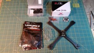
BoltRC Kraken build (K5/K6)

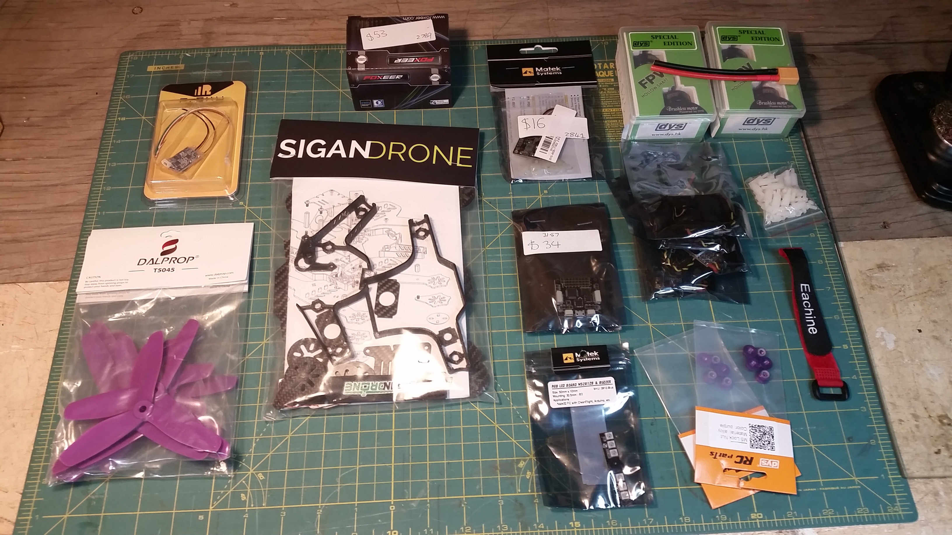
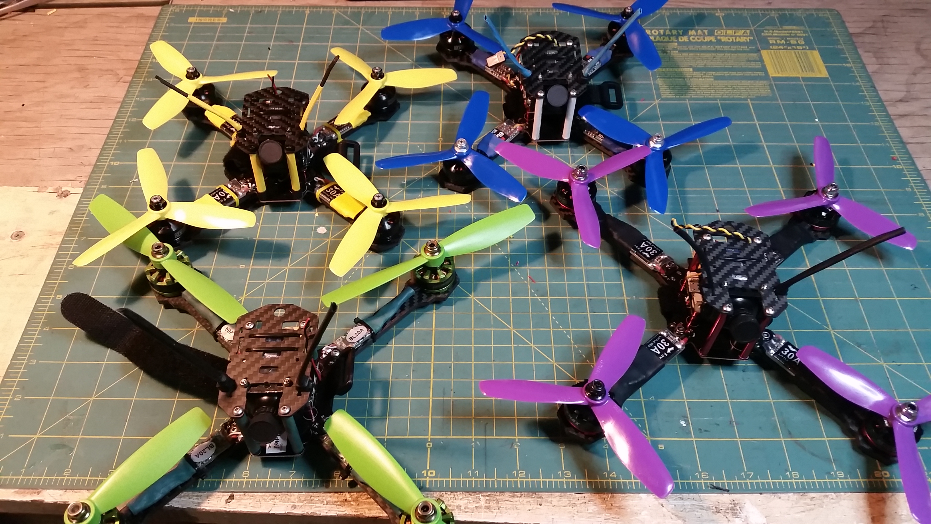
A challenging build due to the need to fit all components into a small area. Not for beginners. Direct soldering to FC and most likely some modifications needed to other parts. Please note there are pictures below from multiple builds where different methods were used. They are not sequential and parts and layout differ from picture to picture.

20160626_034922

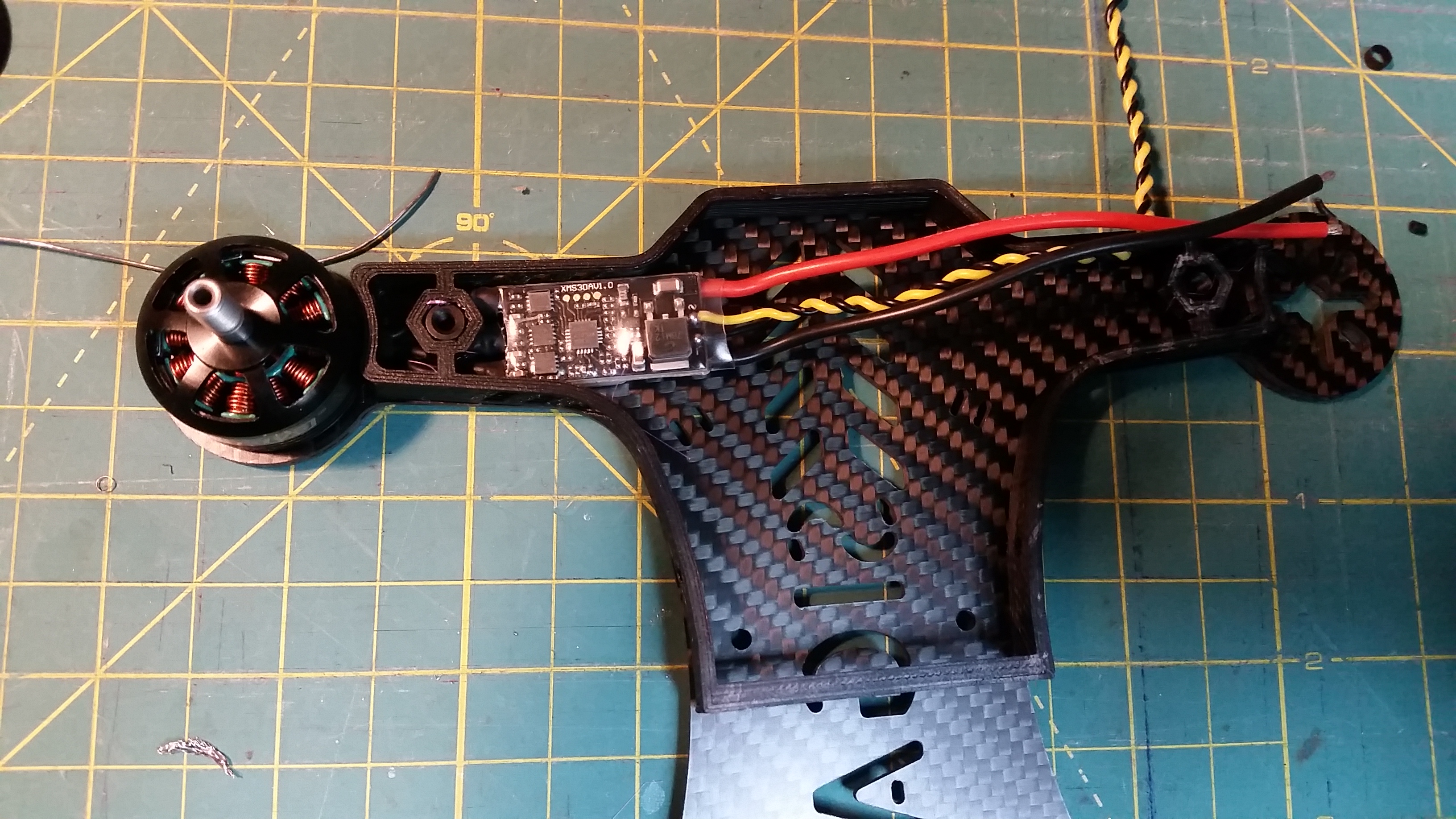
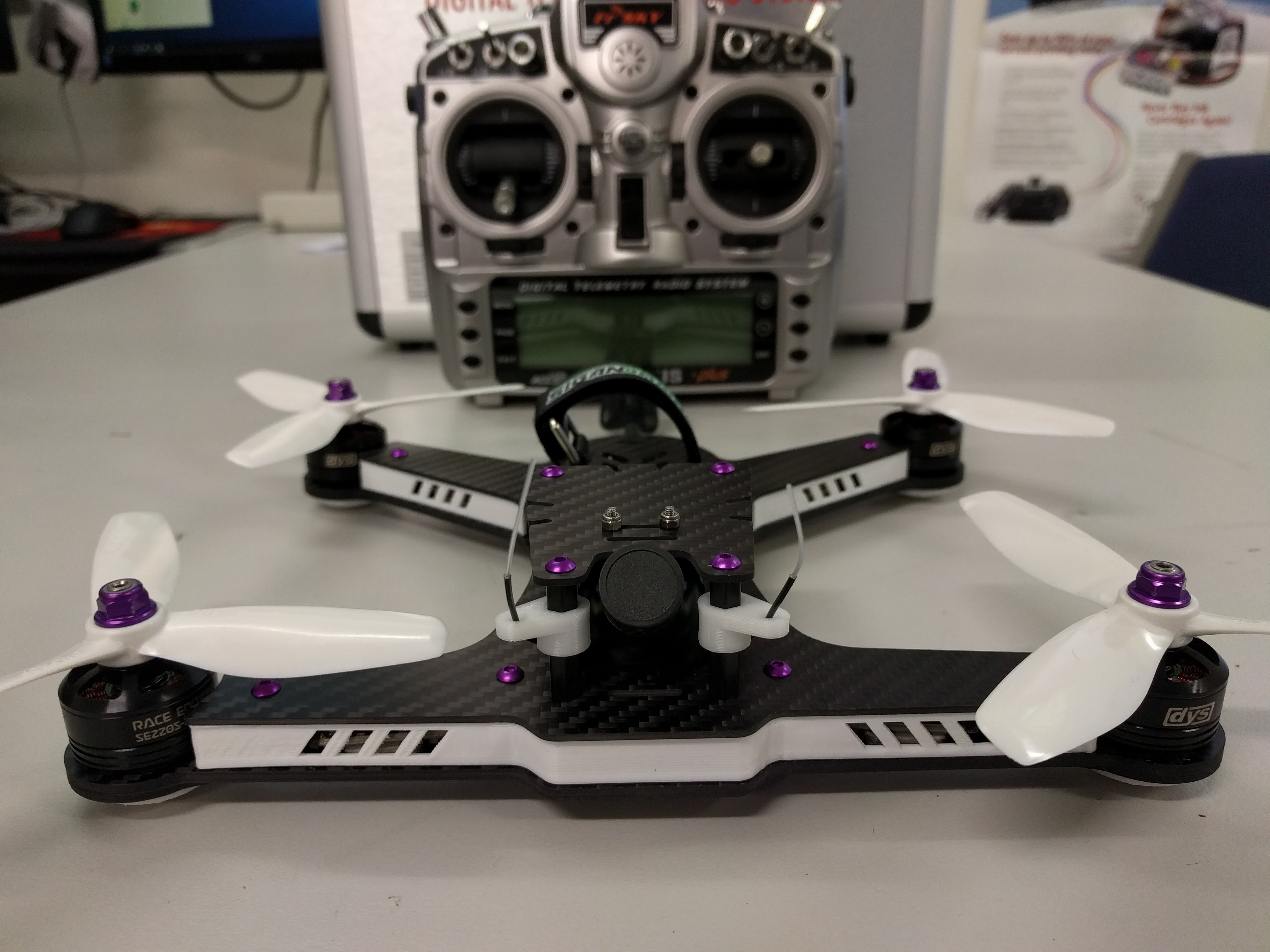
The first decision you will need to may is how to mount and route your motor/ESC wires. There is a few possibilities here with each method having pros and cons.

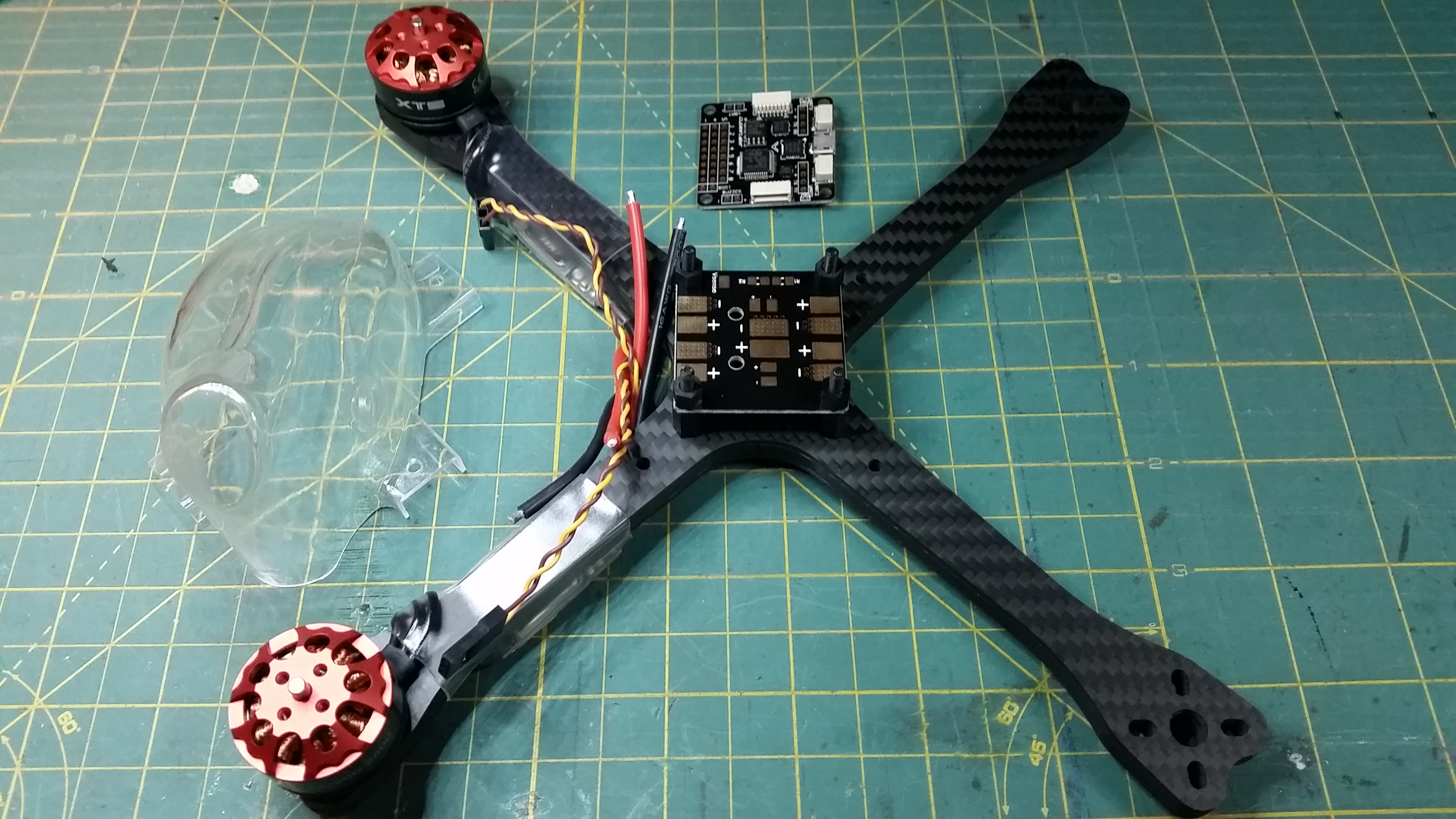
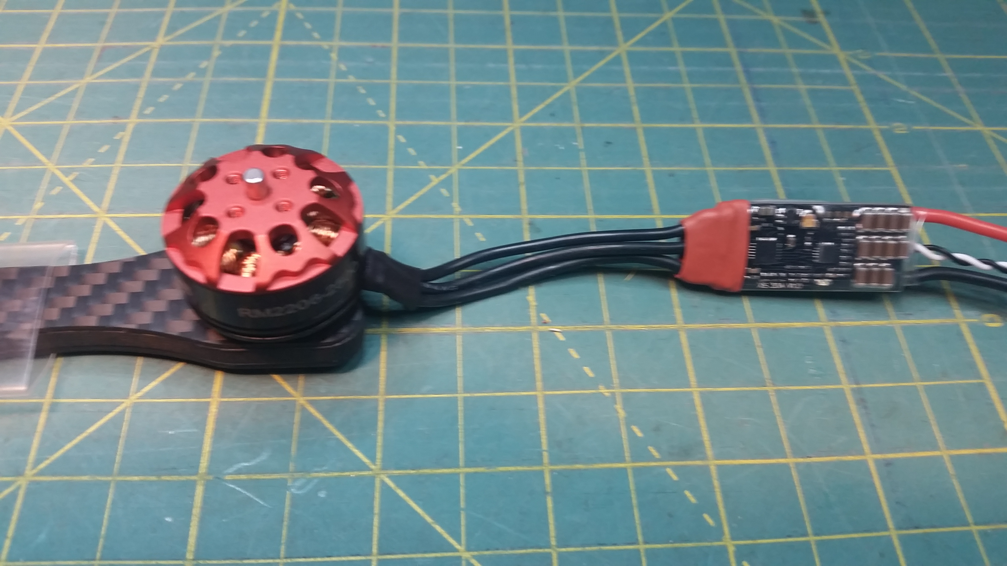
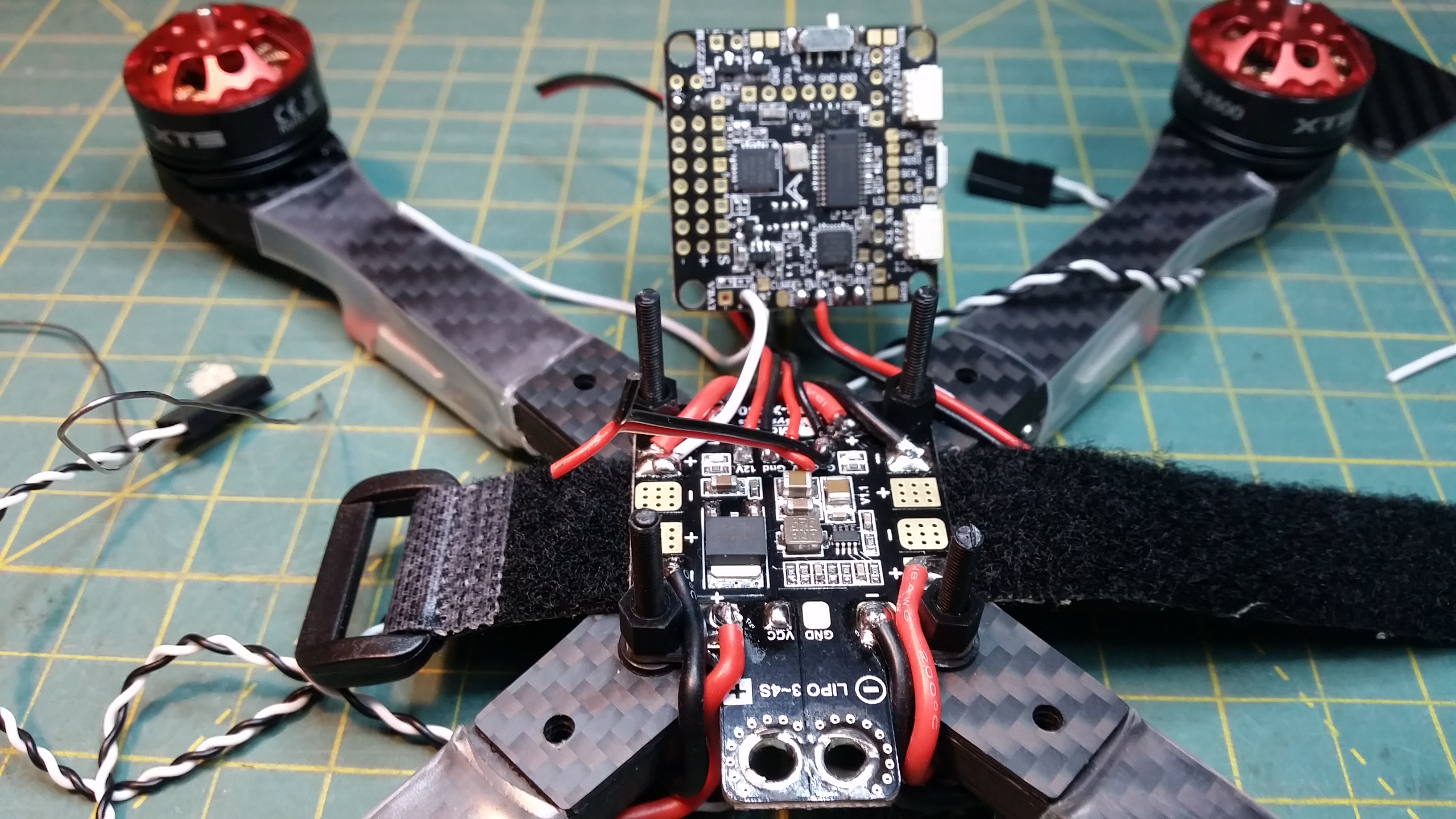
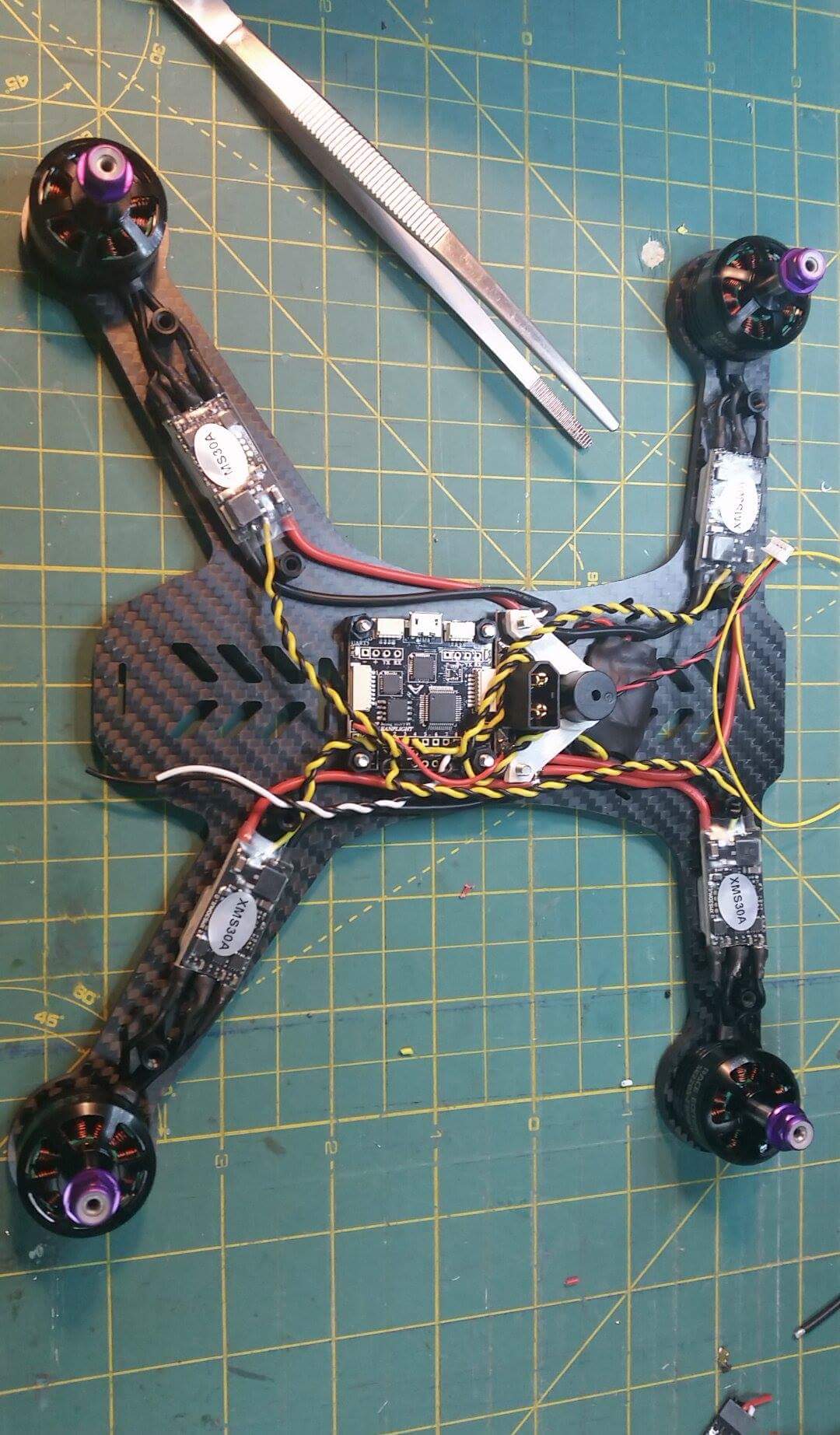
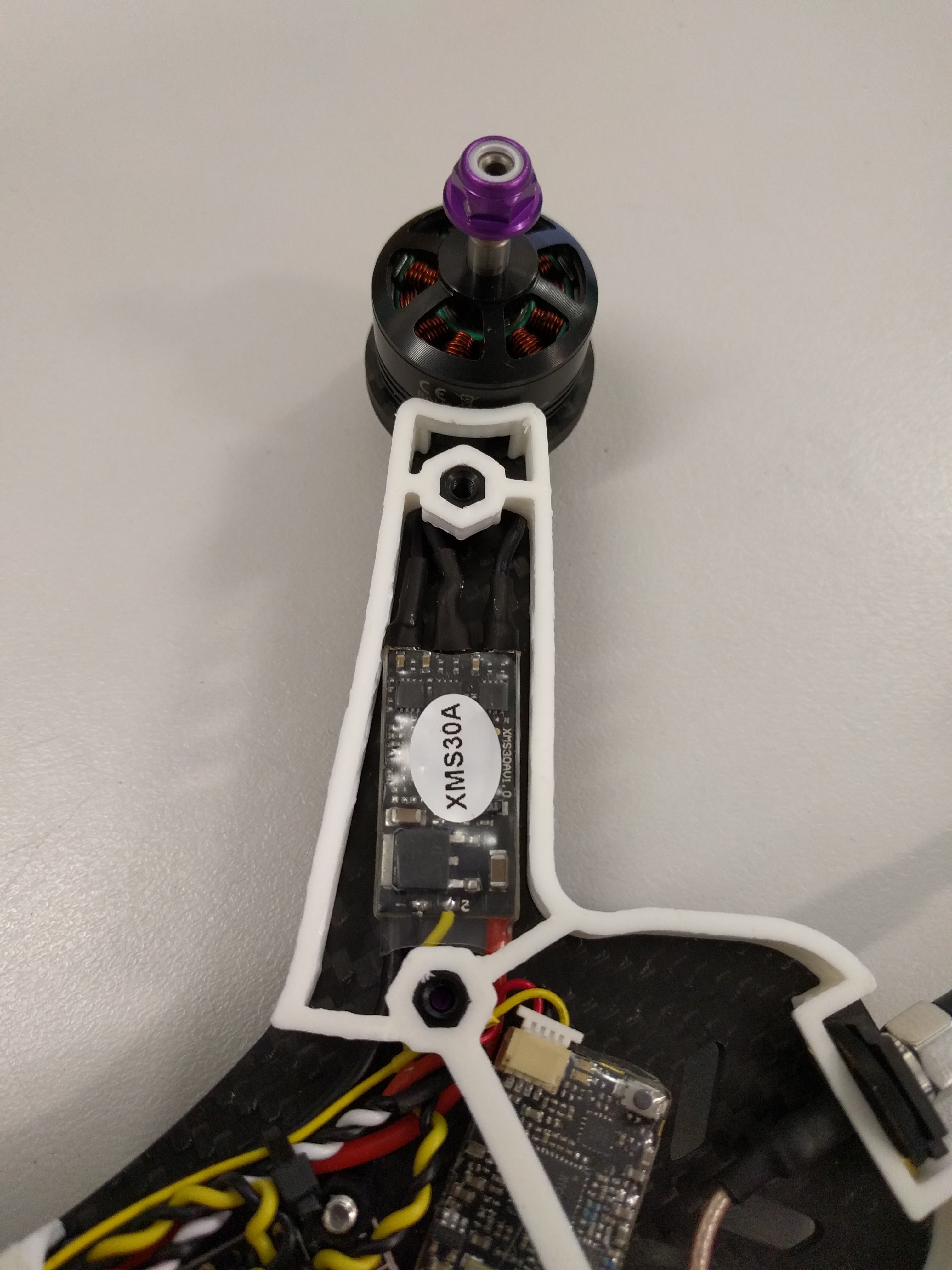
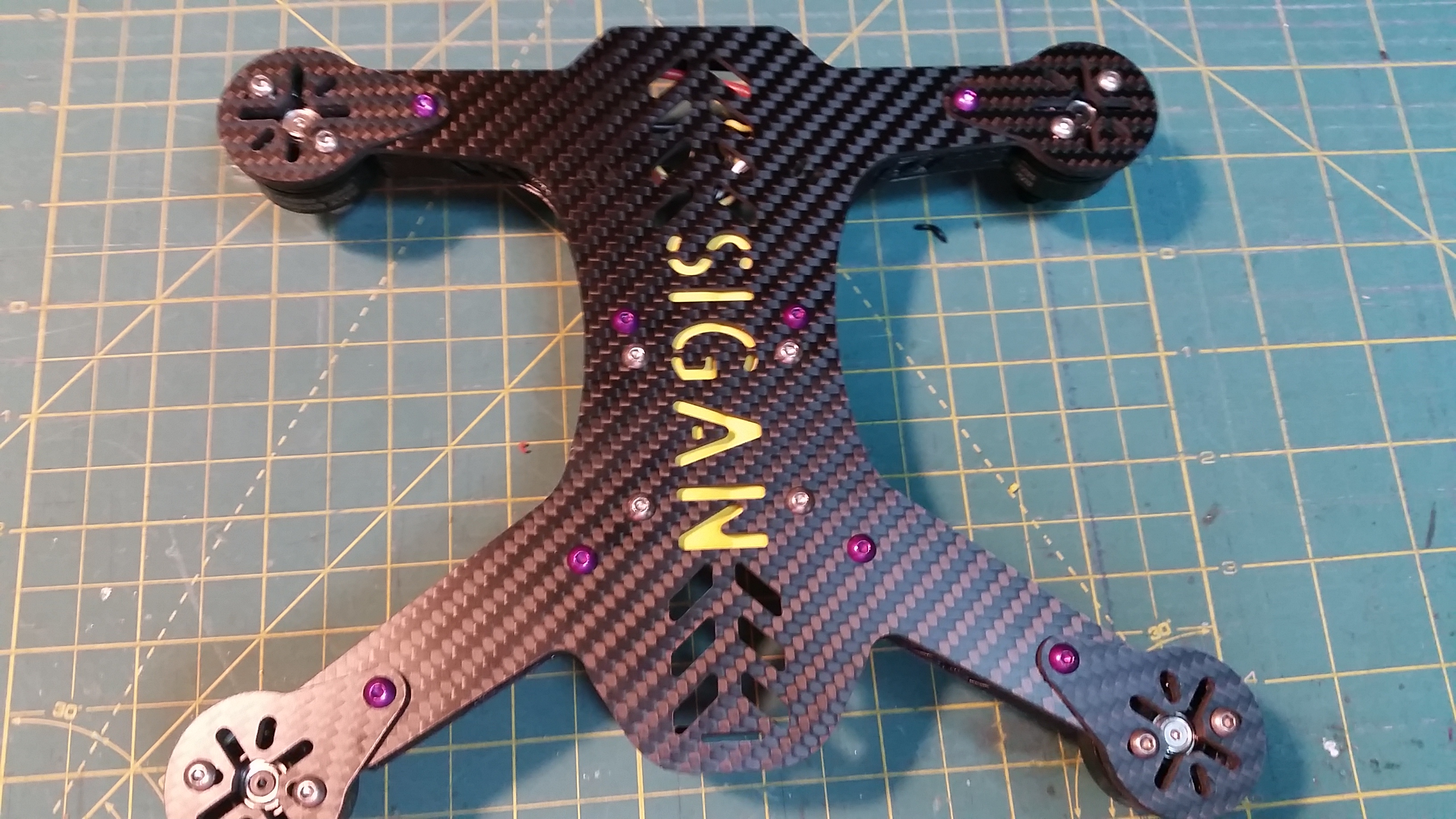
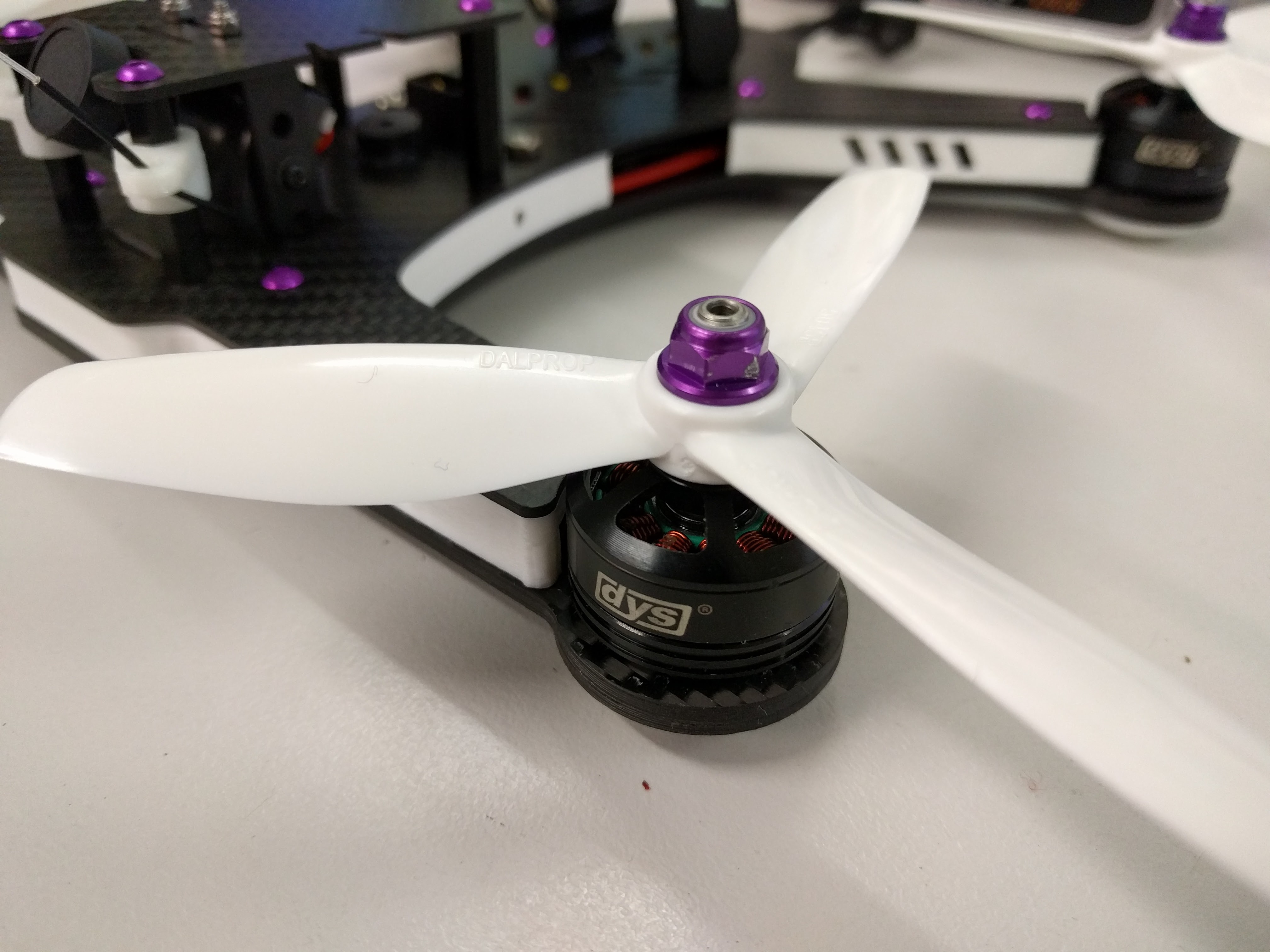
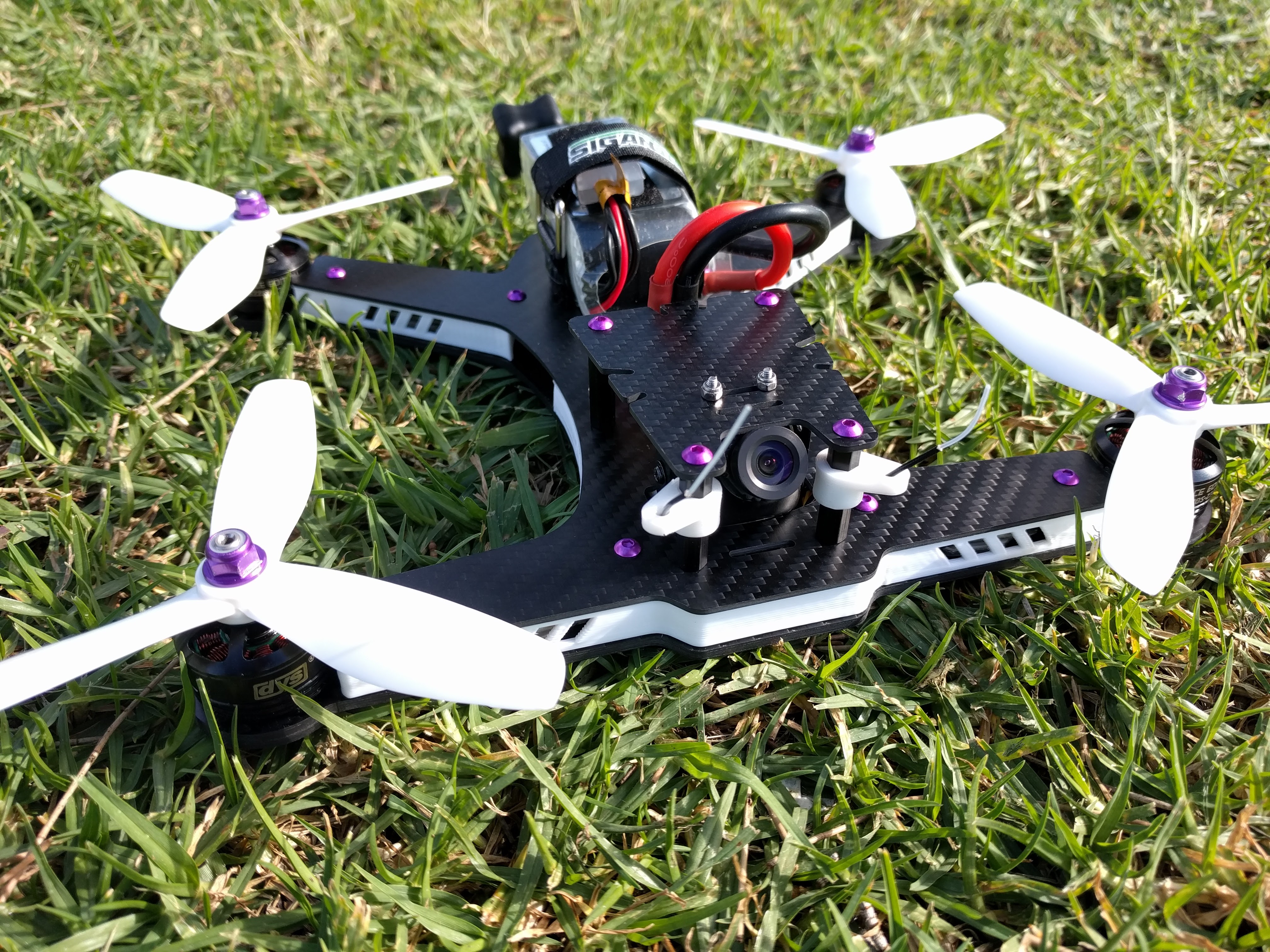
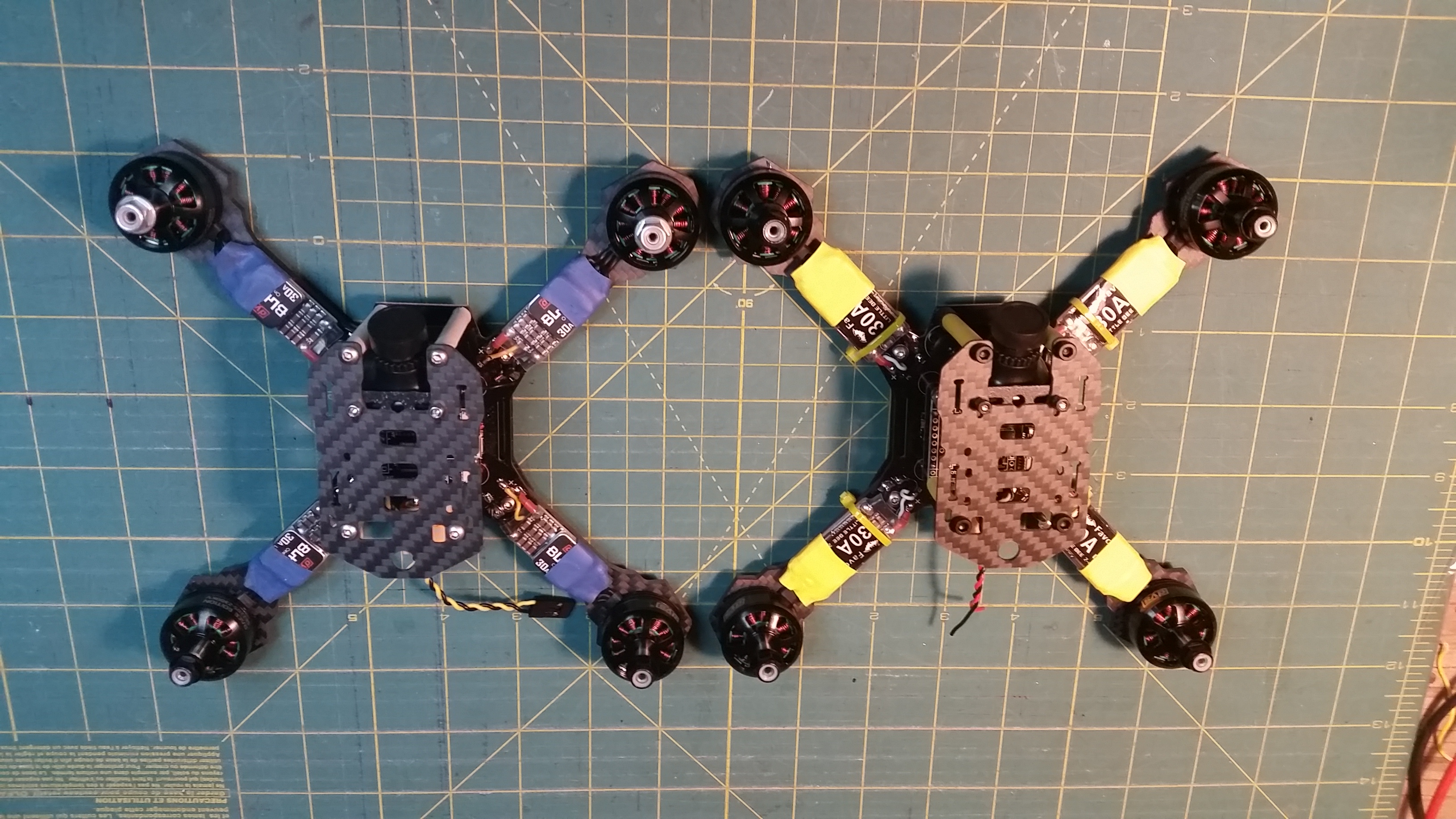
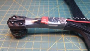
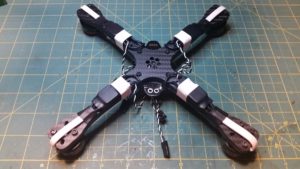
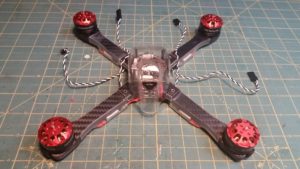
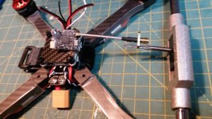
In the picture below you can see the motor is mounted with the ESC wires wrapped around the arm, with the ESC mounted underneath the arm. This can protect the ESC from prop strikes, but also allows for the easy routing of power wires to the PDB, away from the edges of the Lexan shell. If you choose to mount your ESC on top, be sure to allow adequate clearance of the power wires to reach the PDB without rubbing against the shell.

20160626_043618

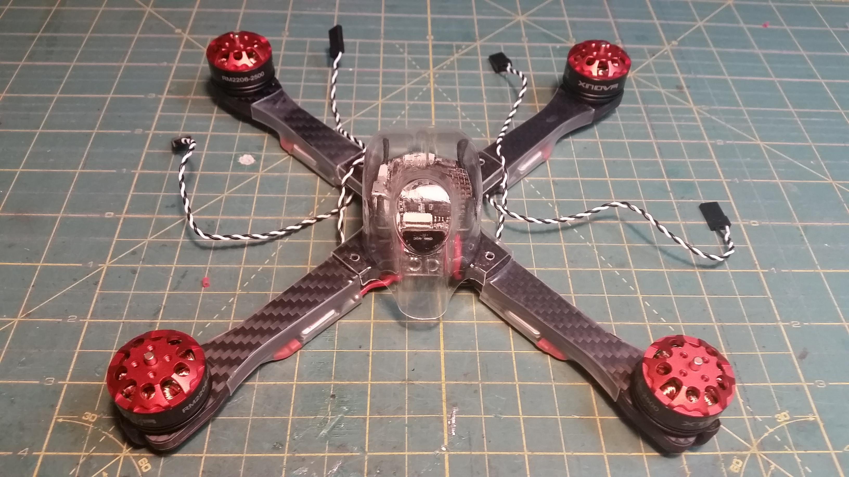
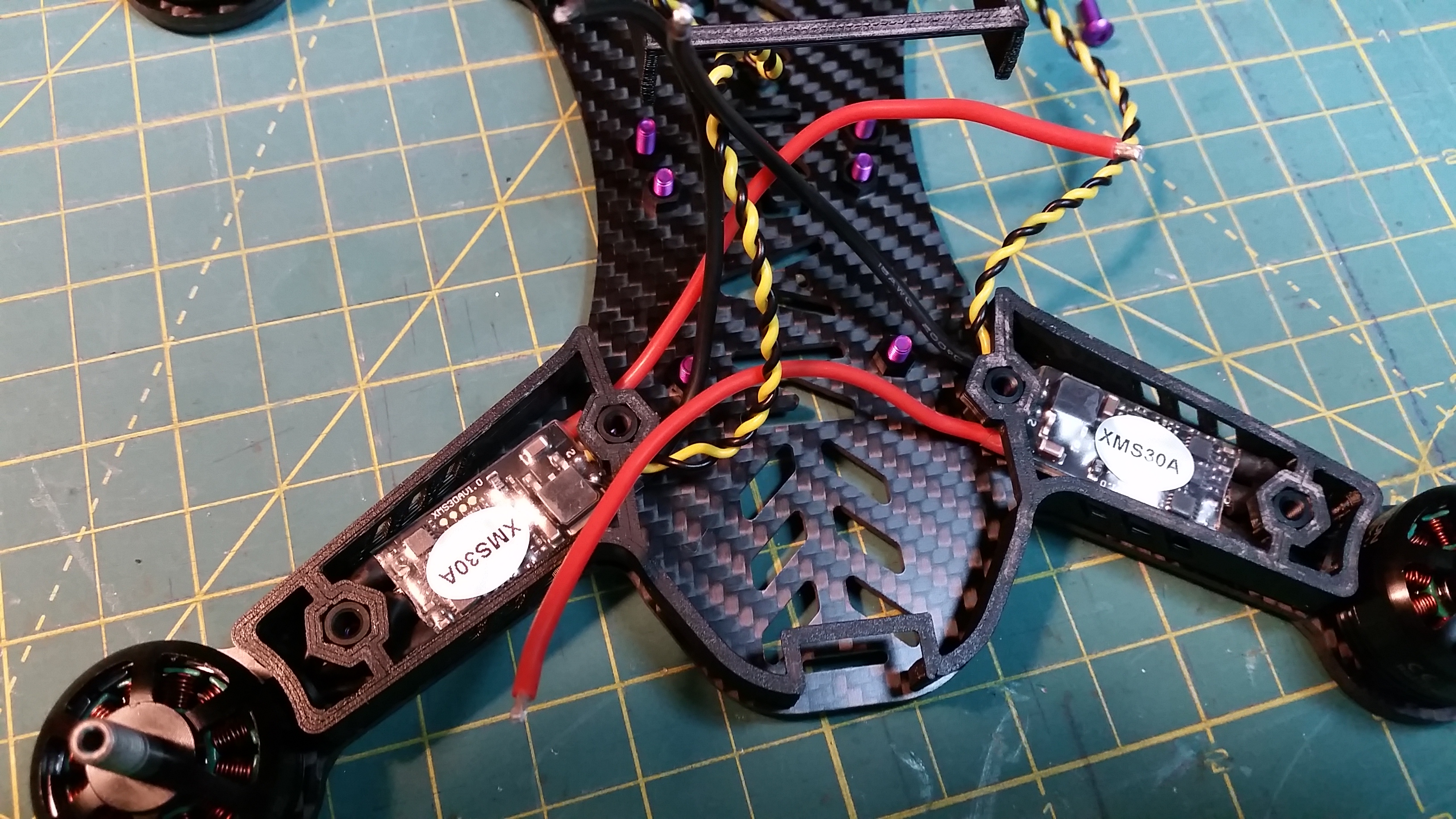
An alternative method is to mount the motor “backwards” with the wires pointing away from the center. Route the motor wires down and underneath to the ESC, making sure to insulate the parts that come into contact with the edges of the frame with shrink wrap or nylon braid.

20160715_062935

20160715_063207

20160726_110333

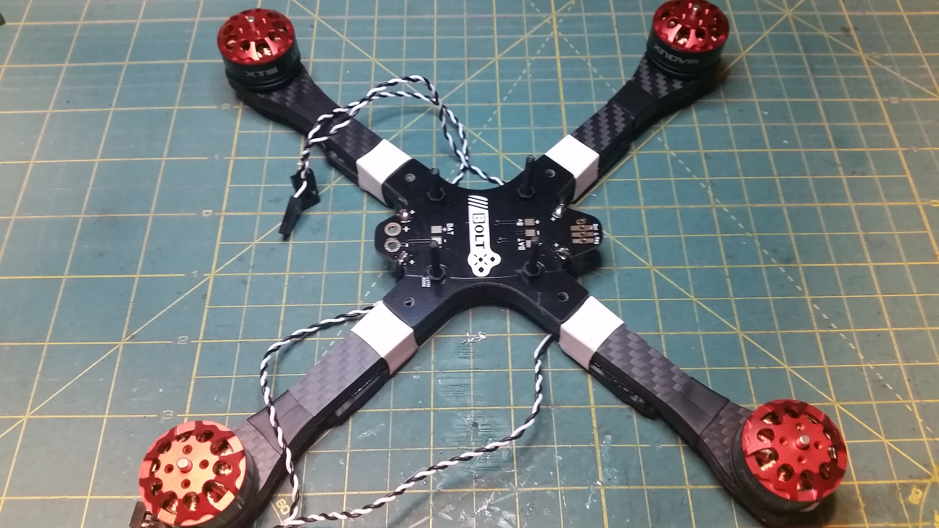
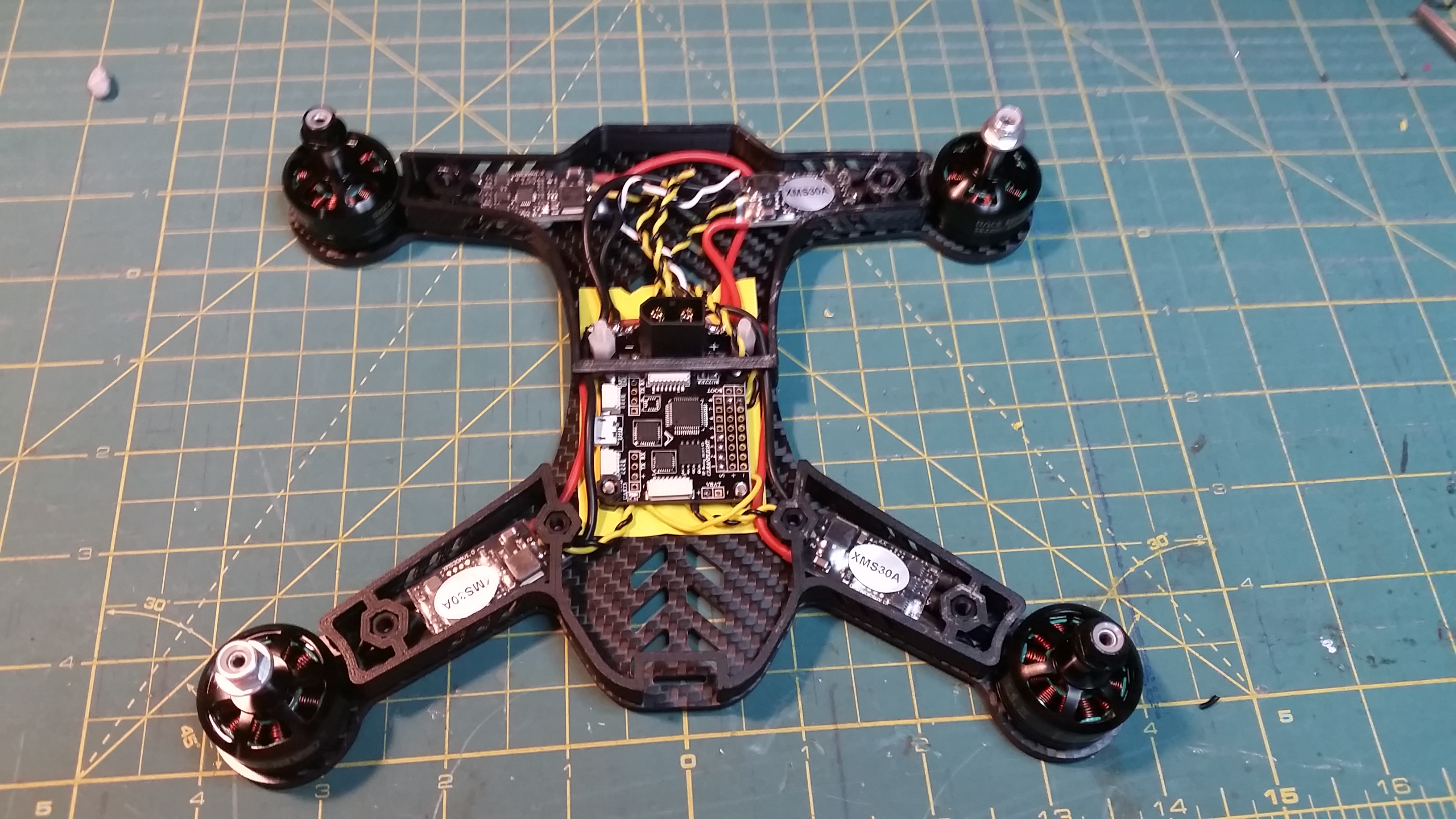
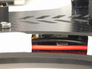
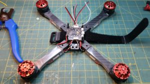
From here you need to mount your ESC making sure you have enough room to clear the bolt holes for the shell and FC stack. Route your ESC power wires up to the PDB, place your shell ontop before you solder to make sure you have enough clearance. You dont have to use the BoltRC PDB but it does strengthen the frame a little more as well as offer some more realestate for mounting extras. Make sure you mount the negative side down onto the frame.

20160726_110339

Please note, the provided regulator on the PDB is for 8v. If your FC or other components require less you will have to add further regulators.

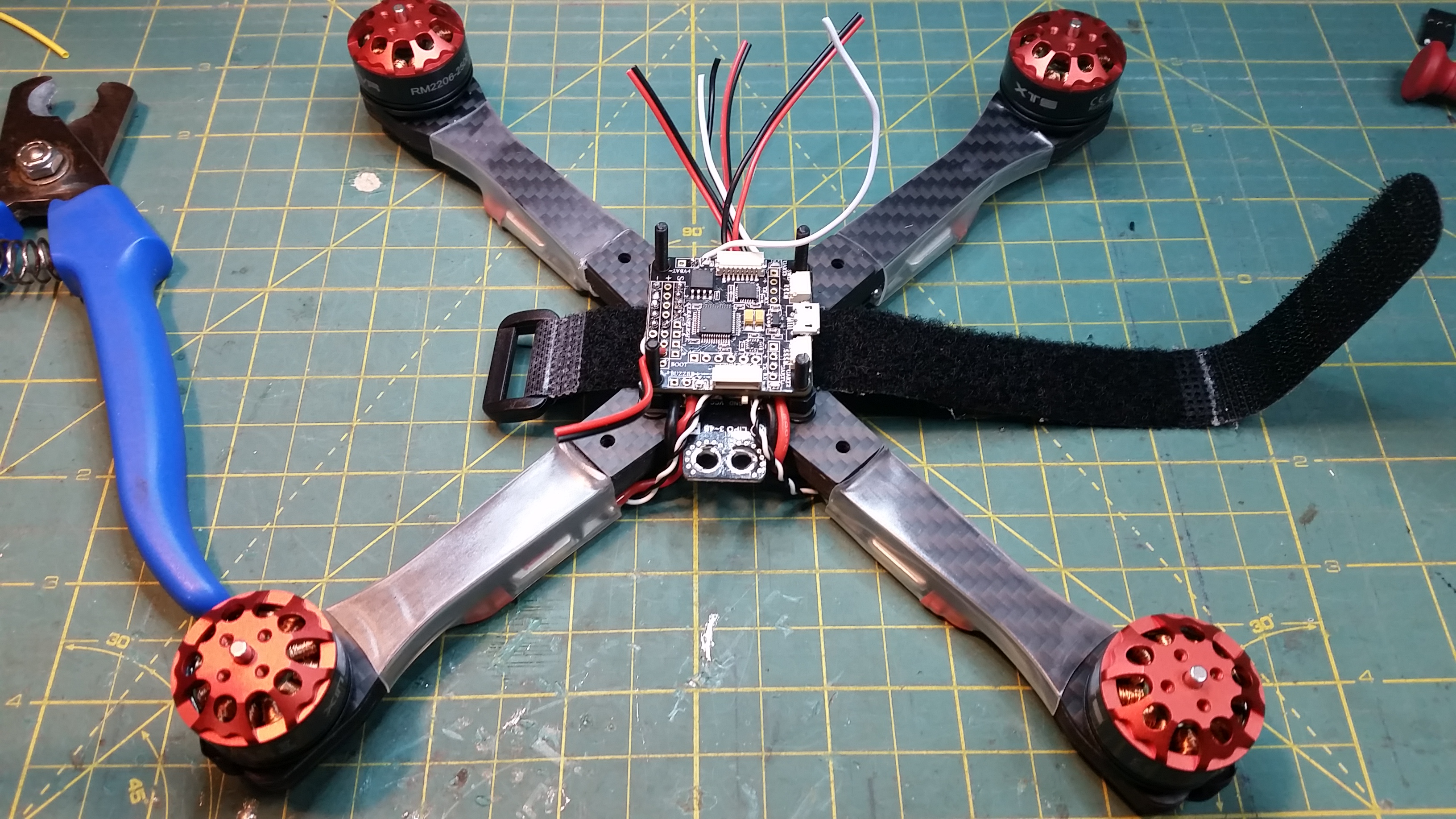
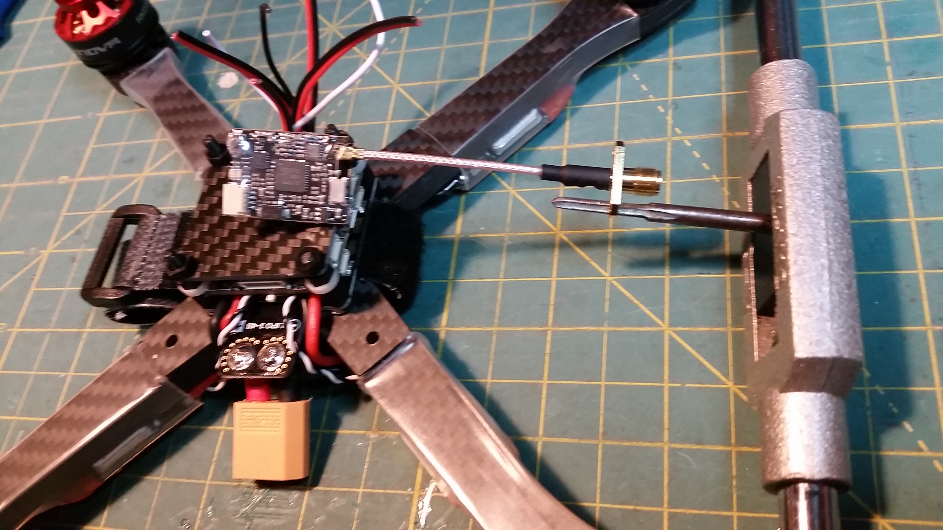
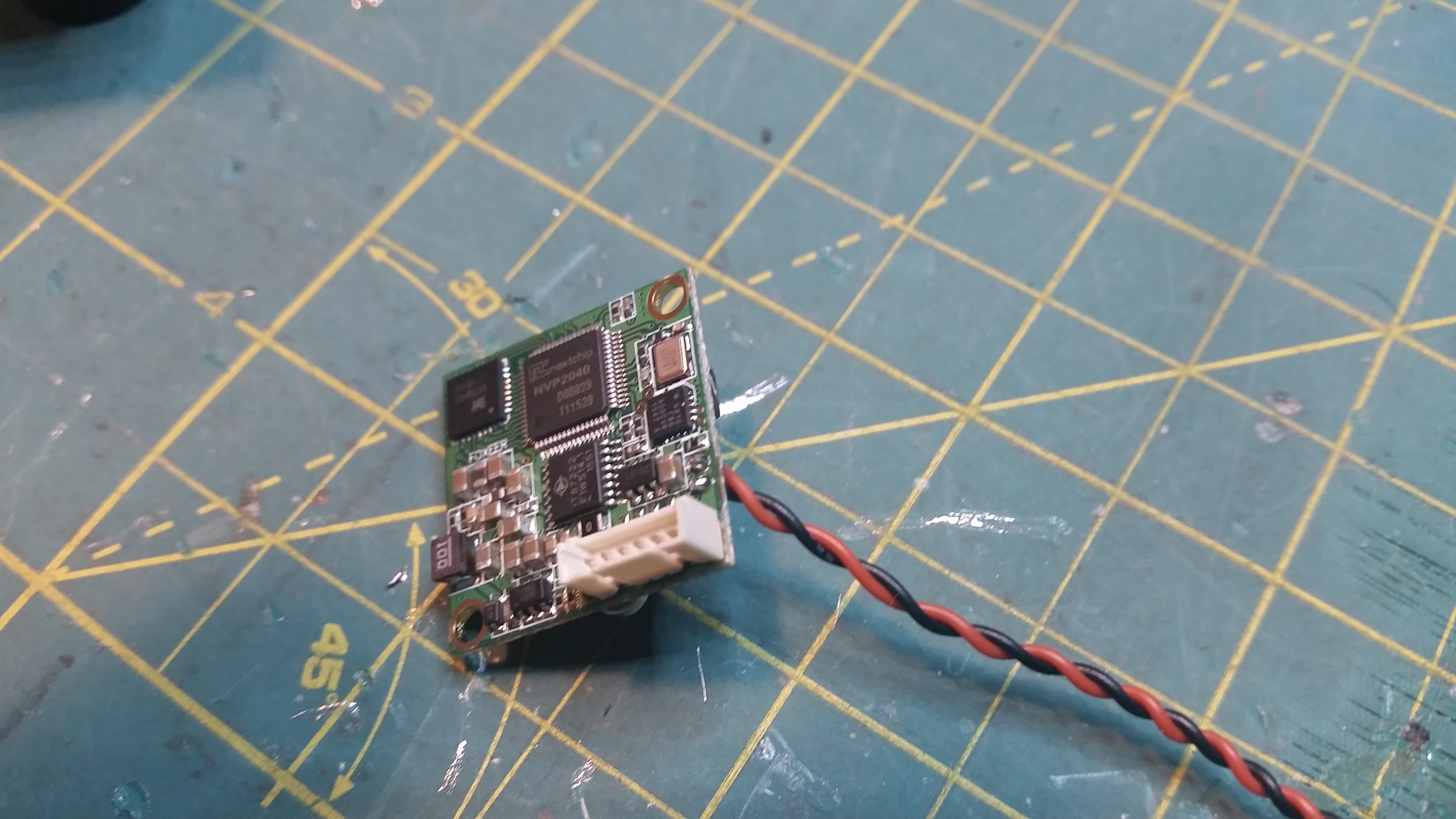
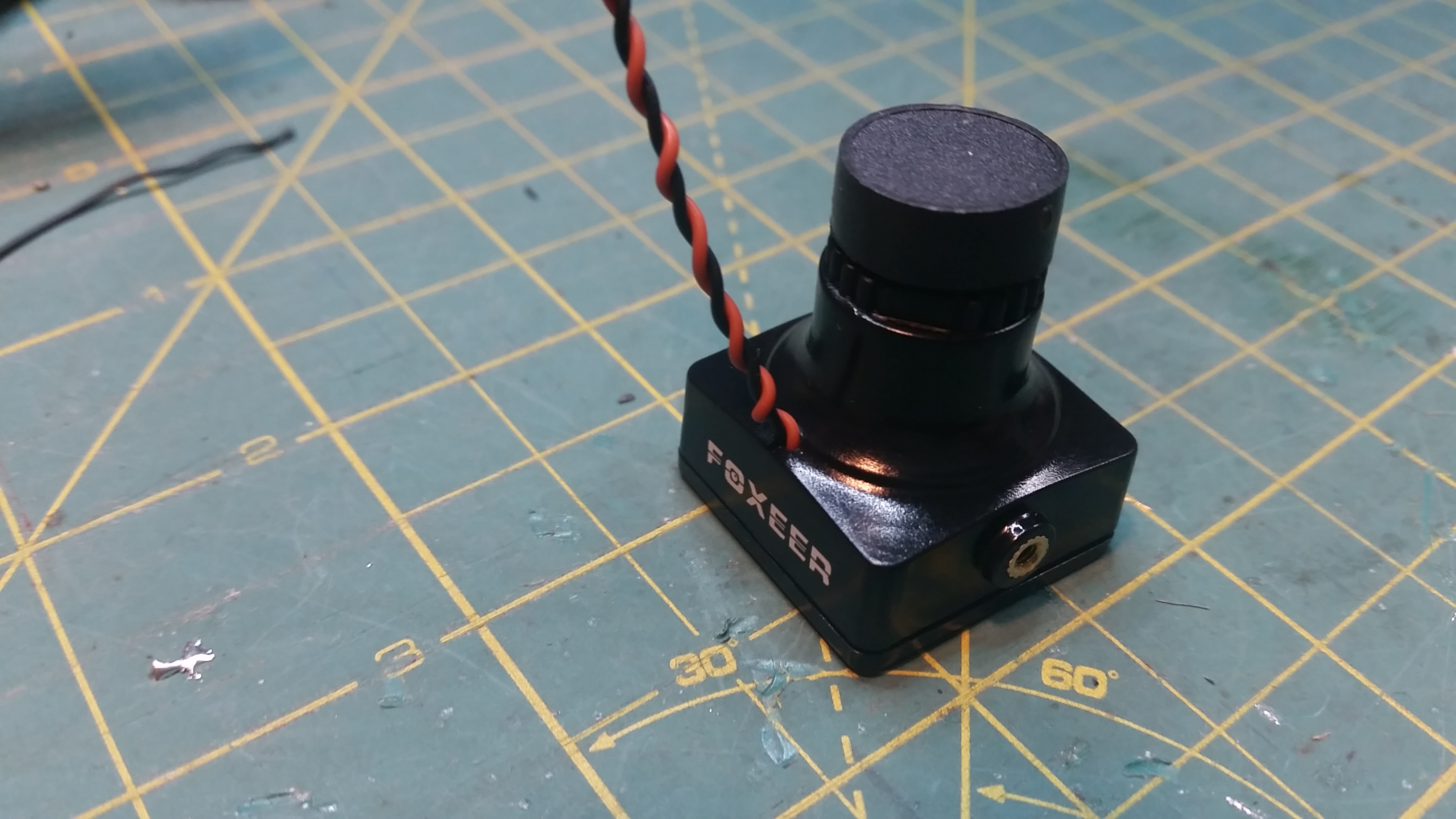
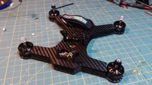
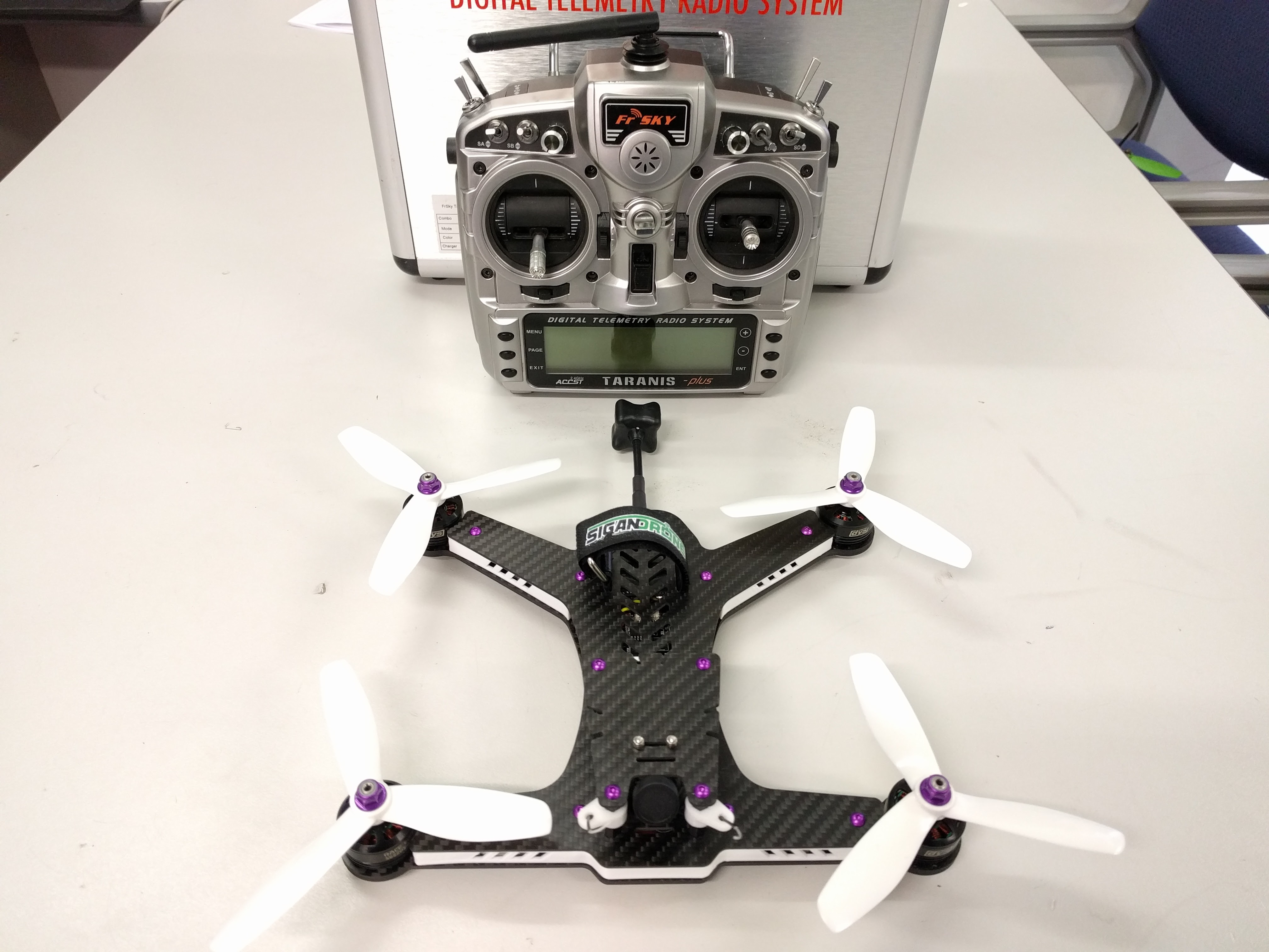
Once your PDB is mounted its time to layout your FC stack. I recommend doing a mock up of this to check that everything you have will fit. To be extra thorough mount your camera with the supplied bracket inside the shell and slip the shell over the top to check clearances.

20160715_075812

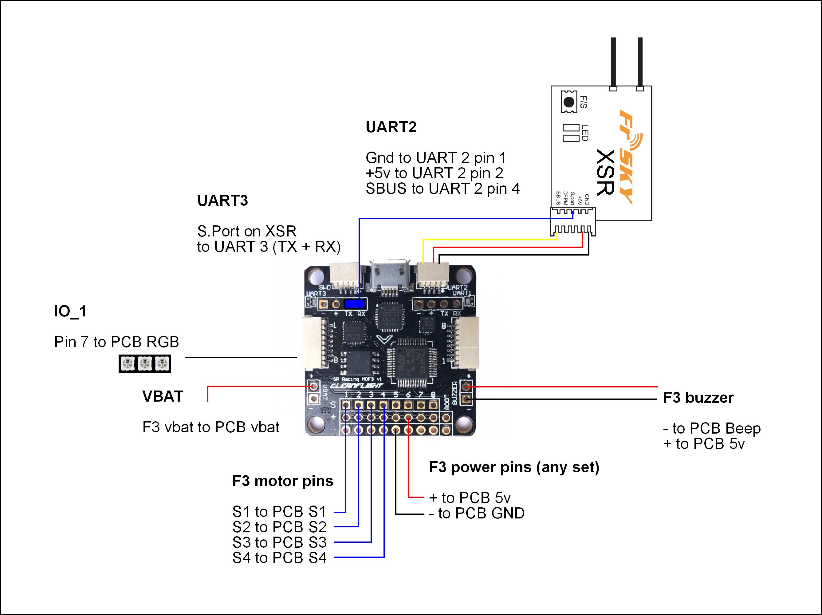
Consider mounting your strap at this stage then placing your FC over the top. Space your FC with the included spacers so it does not come into contact with the PDB. Be as minimal as possible.

20160716_120639

Keep all your leads to the FC as short as possible.

20160716_114011

If you want to cut a slot in your shell so that the FC port is accessible make sure to orientate your FC accordingly.

20160716_131158


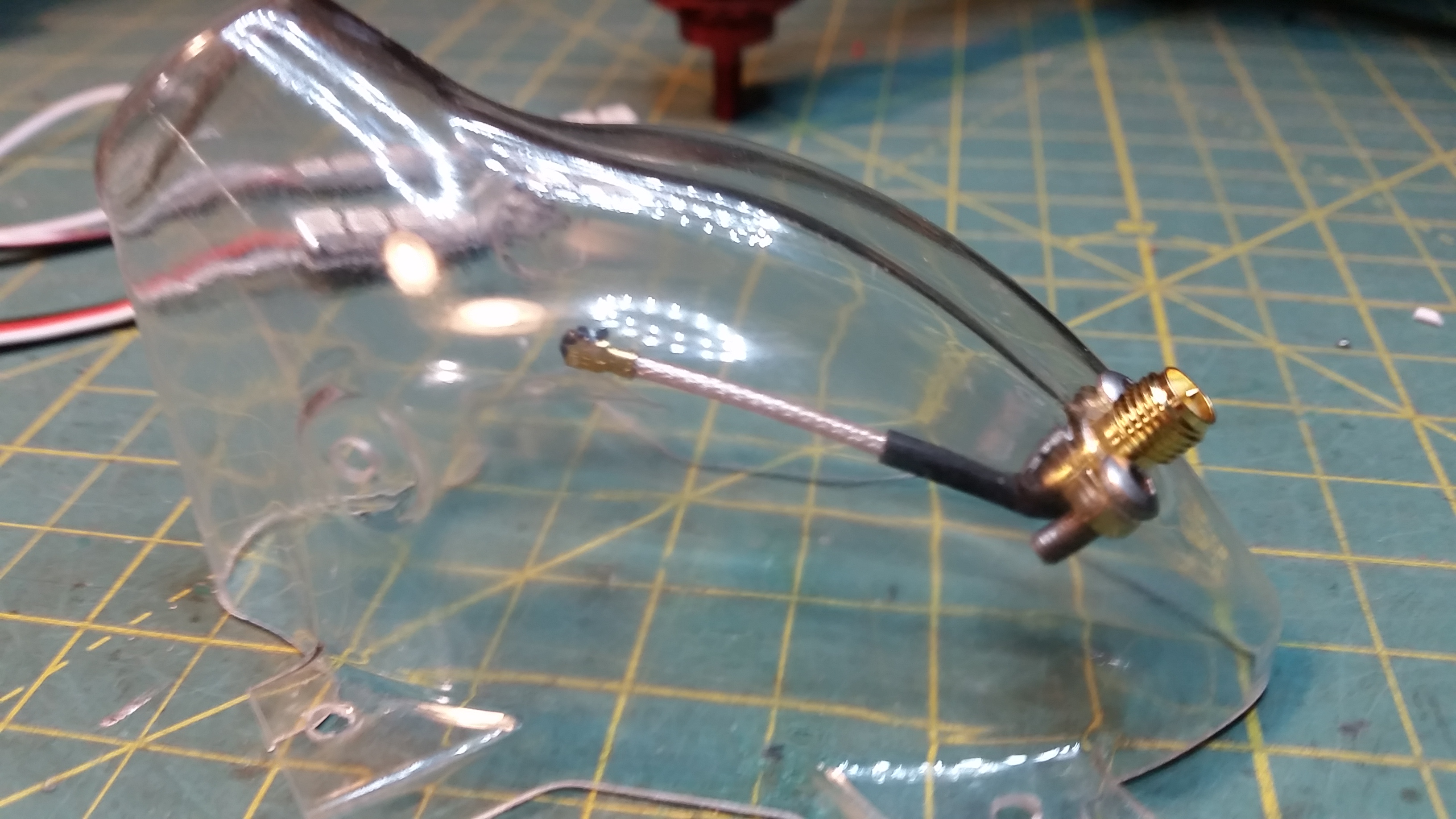
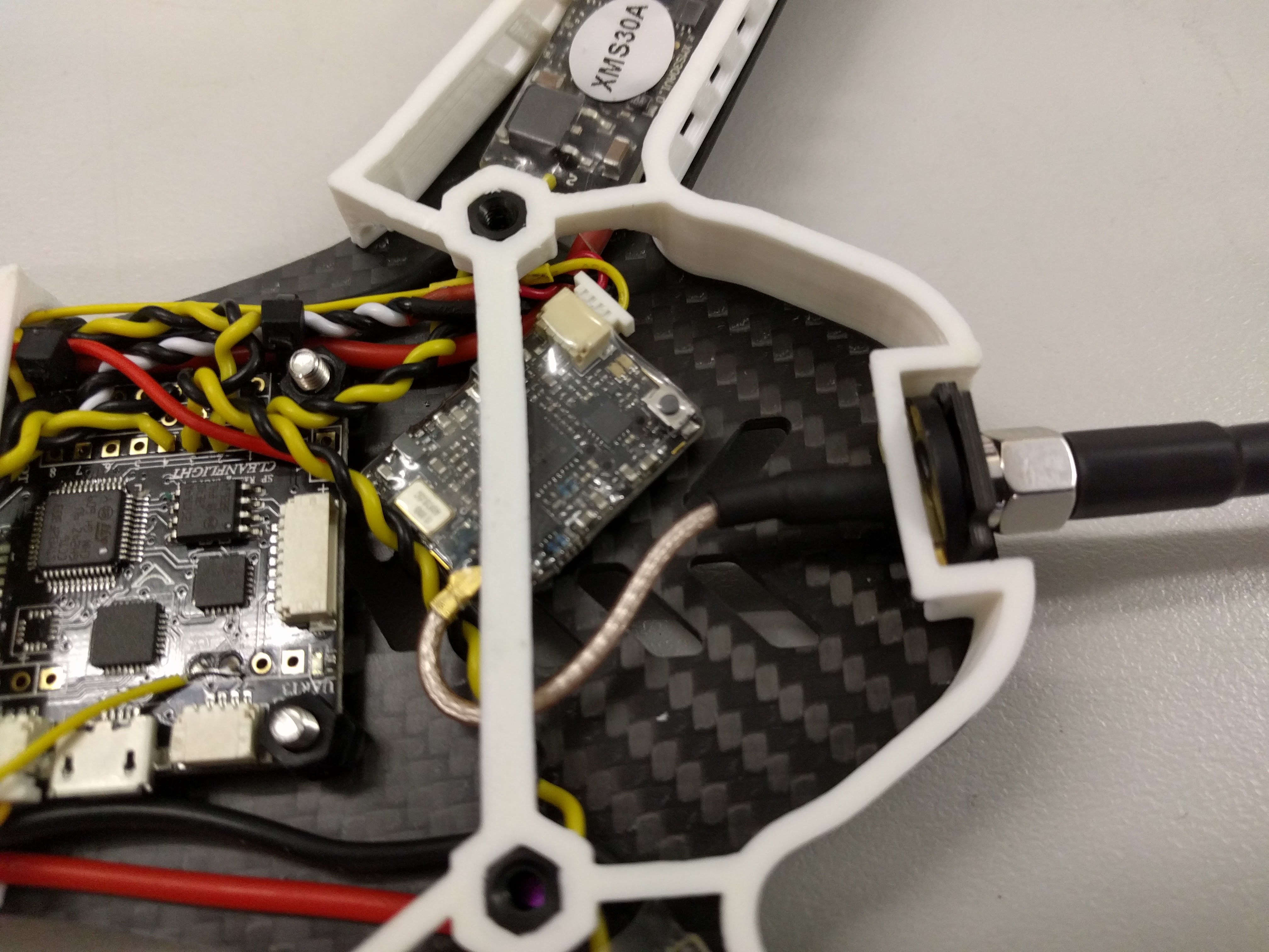
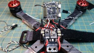
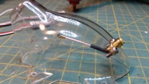
Here you can see some modifications being done to the TBS unify VTX. Ive added a small carbon plate to the top of the FC stack, available from Phaser for a few dollars. It allows for the mounting of the VTX/RX and 5v reg if required.  The RX is mounted on the underside of the Carbon plate with the VTX and reg on the topside. Alternatively you can mount some of your hardware to the shell itself, make sure you make it easy to disconnect if you do. Check clearance on your VTX antenna, the TBS pigtail will need to be modified to clear the FC stack. Or you may chose to replace it with a 90 degree pigtail.

20160718_104654

Once you have all your clearances sorted out you can begin porting the shell for your camera. Use a soldering iron to get started and clean the edges up carefully with a file or dremel. Careful, the lexan marks easily and can crack if you are rough.


Foxeer Arrow CCD with OSD voltage Setup Wiring Diagram

Just a quick post for those who may be trying to get the OSD voltage on the Foxeer Arrow CCD camera.

You can run power straight from the battery to the camera (5-22v) and it will display the voltage but the manual suggests a regulated voltage for the input, especially if you have active braking enabled. So running regulated voltage to the camera is recommended, but now our OSD voltage will be a constant voltage and not reflective of the sources voltage.

To get around this you need to remove the back cover, revealing the circuit board. Just below the positive terminal of the plug you will see two copper tabs/perforations, marked + and –

20160629_150808

Run two tiny wires from these tabs through the hole on the front of the case and route them to your source voltage on the PDB. When these wires are connected it will display voltage from here by default.

20160629_151141

Happy voltage monitoring.

How To Charge The Fatshark Battery 7.4v 1600mAh Properly

You may notice that the Fatshark battery has DO NOT BALANCE CHARGE on the balance Lead.

This is because the battery has its own balance circuit so it does not need balance charging.

IMG_20160615_221756

You may get an error that says “Balance Connect Error”
Some chargers still need the balance lead connected to the charger even though it’s not balance charging.

The correct way to charge is LIPO charge and 1C would be 1.6amps like below picture

IMG_20160615_221740


If you have an advanced charger, it may also check the resistance. The battery will show high resistance, this is normal because of the balance circuit and you may ignore it.

Sigan 250 Build Log

1. Components

Total Cost – $629.70 + $6 hours labour + Consumables.

2. Tips On Building

The Sigan drone is an award-winning compact racer with a very specific design requiring a tight and compact assembly of the electronics. It should not be attempted for those who are new or inexperienced in the craft. The build pics below are from the 210 and 250 class available from Phaser computers.

If you decide to use different components than those listed above please check to see if they will fit. The space between the top and bottom plates is around 10mm. Since all components bar the camera, buzzer and xt60 are intended to fit in this space anything higher than 10mm is essentially a problem.

20160601_11213620160601_112419

Once you have checked all your parts are there I recommend inserting your standoffs first and test fitting your escs. 20 amp esc’s are recommended for the 210 build, though the right 30 ampers can fit if you are careful. The 210 seen below has 30 amp DYS escs with solder tabs. Take special care when soldering the middle motor lead in particular, it will need to be slightly longer to accommodate wrapping around the body post. Test fit your 3D printed side skirt/bumper too, if your esc doesn’t fit inside you may as well stop now until you solve that. Everything should lay as flat as possible, motor leads will need to be short and soldered directly to the esc, especially in the case of the 210.

20160604_21234720160604_223122

Mount your flight controller next. -90 or +90 so you can access the usb port. You may choose to use some longer bolts for the pdb and FC. There are holes on the top deck that line up with the pdbs bolts and I chose to lengthen these bolts to stiffen the pdb and center of the drone. When you solder in your xt60 connector remember to trim the bottom tabs off flush so they dont rub against the carbon fiber and cause a direct short. This will most likely end very badly if you aren’t careful.

received_23589864346238620160605_122107

Route all your power cabling down either side of the craft to the PDB, leaving enough room for the 3d printed skirts to fit and allowing access to the FC usb hub. Solder all connections directly to the FC where possible. Use the 5v regulator to power your FC and any other components like the VTX in this case.

3. Final Build Pictures

IMG_20160615_103512IMG_20160615_103518IMG_20160615_103509IMG_20160615_112455IMG_20160615_11251920160605_12213720160605_122213IMG_20160615_112500IMG_20160615_112443IMG_20160615_112526IMG_20160615_120156IMG_20160615_120149

Custom Quad Builds – Taranis Sound Pack and Uploading Preconfigured Models To Taranis X9D

Please note that this guide was created for our custom builds for Customers so they can simply drag in our models, bind their receiver to their new quad and start flying.
You may use these models as templates for your own quads but we will not be responsible for any mishaps you cause.

How to upload Taranis Sound Pack

  1. Hold the YAW RIGHT trim and ROLL LEFT TRIM (Mode 2) together and turn on Taranis
  2. Plug in USB to back of Taranis
  3. It should now appear as a folder under My Computer (Windows)
  4. Download Sound Pack here.
  5. Extract it on your computer.
  6. Upload it to DRIVE LETTER:\SOUNDS\en
  7. Success! – Keep Taranis Plugged in for Next Step

How To Upload Our Models To Your Taranis

  1. Make sure you have Taranis Open TX Companion Installed
  2. You may also need the driver “ST Virtual COM port driver V1.3.1 for Taranis CLI” from that same link above (at the bottom of the page)
  3. Launch Open TX Compansion
  4. Click Read Models & Settings From Radio
    2016-06-07 18_41_50-OpenTX Companion 2.1.7 - Radio_ FrSky Taranis Plus - Profile_ My Radio
  5.  Now you should see a window with your models.
  6. Now download our Model Pack Here
  7. Go back to Open TX Companion and go to file—> open and select the file you just downloaded.
    2016-06-07 18_58_11-OpenTX Companion 2.1.7 - Radio_ FrSky Taranis Plus - Profile_ My Radio
  8. You should now have another window to the right with our Models.
    2016-06-07 22_53_23-OpenTX Companion 2.1.7 - Radio_ FrSky Taranis Plus - Profile_ My Radio
  9. Simply drag our models across to slots on yours
  10. When you are done, close our models and go to the menu at top —> Read / Write —> “Write settings and models to Radio”
    2016-06-07 18_59_41-OpenTX Companion 2.1.7 - Radio_ FrSky Taranis Plus - Profile_ My Radio

NOTE: Once you are using our Taranis model and betaflight setup below, this is the switch configuration

CH5 = AUX 2 = ARM = SF
CH 6 = AUX 1 = Modes = SC
CH 7 = AUX 3 = Air Mode/Buzzer = SD
CH 8 = AUX 4 = Nothing Setup = SA
CH 9 = AUX 5 = LED Strip = SB
CH 10 = AUX 6 = Nothing Setup = SE

Other Features
S1 is volume of your Taranis
All Switches tell you when armed, disarmed and what mode etc.
SH Switch says current Battery Voltage
Voltage warnings will occur at 14.4, 13.6 and 13.65
SG Position 2 and 3 will play your favourite songs
SE Position 3 will cheer your mates when they crash.

Cleanflight Backups of prebuilds we have done

Please note that these are full restore settings for Firmware listed.
These can be used as a base for your tune as well, however no two crafts fly the same due to many variables such as battery weight and other factors
These are also set up to mirror our Models from Taranis as per above, so please check all your modes/switches if using different transmitter/setup.

Screenshot of how modes should be setup if using Taranis Profile

Betaflight:
cleanflight_modes_taranis_setup

Cleanflight
cleanflight_modes_1
cleanflight_modes_2

Emax X5 – Cleanflight 1.13 |EMAX F3 FC SBUS

Emax X5 – Cleanflight 1.13 |EMAX F1 + OSD FC PPM

Emax X6 – Betaflight 2.8 – Coming Soon

Sigan210 – Betaflight 2.8 – Coming Soon
Sigan250 – Betaflight 2.8 – Coming Soon
BoltRC Kraken – Betaflight 2.8 – Coming Soon

Eachine Falcon 180 RTF Naze32 Review – Guide To How It Should Have been Setup – With Cleanflight

Last Updated 14th June 2016

Here I will address quite a few problems with the Eachine Falcon 180, and walk you through fixing them.

If you have never upgraded or used Cleanflight, the details may be very technical, but I will try my best for step by step instructions.

Let me address some of them here as well as screenshots of all the default settings at the bottom. I will attempt to rectify and help Blade185 buyers fix most of the issues I have found. Continue reading “Eachine Falcon 180 RTF Naze32 Review – Guide To How It Should Have been Setup – With Cleanflight” »