This guide is designed to walk you through flashing MWOSD software to any OSD board, or update to a newer version.
There are many ways of configuring your inbuilt OSD and many different variations of the software you can use. It is compatible with Multiwii software intended for Minim OSD, which comes as a standalone chip. With it integrated into the flight controller you are able to minimise your wiring and layout, and monitor all sorts of details from your craft. Specific versions allow for direct links to Cleanflight, using data from the FC itself to minimise connections. It also allows for customising the look of your OSD including layout, features and fonts used for display.
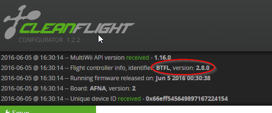
This tutorial will cover the reflashing and setup of the OSD part of the FC. The FC itself is setup as normal. Note that the OSD is not configurable via USB connector. This is reserved for FC configuration. There is also a switch on the FC itself, this switch must be off if one wishes to configure the FC via USB as the USB and OSD share the same UART port. If you have unusual sluggish behaviour or inability to connect via PC the chances are the switch is on and must be switched off. Inversely, if you are ready for flight but have no video feed you may have forgotten to switch the OSD back on after configuring via Cleanflight/Betaflight/Raceflight, assuming your setup is correct.
For simplicity we will only look at a few vital features here. You can experiment at your leisure with some of the more advanced ones.
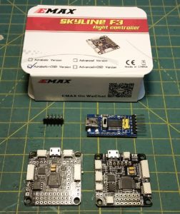
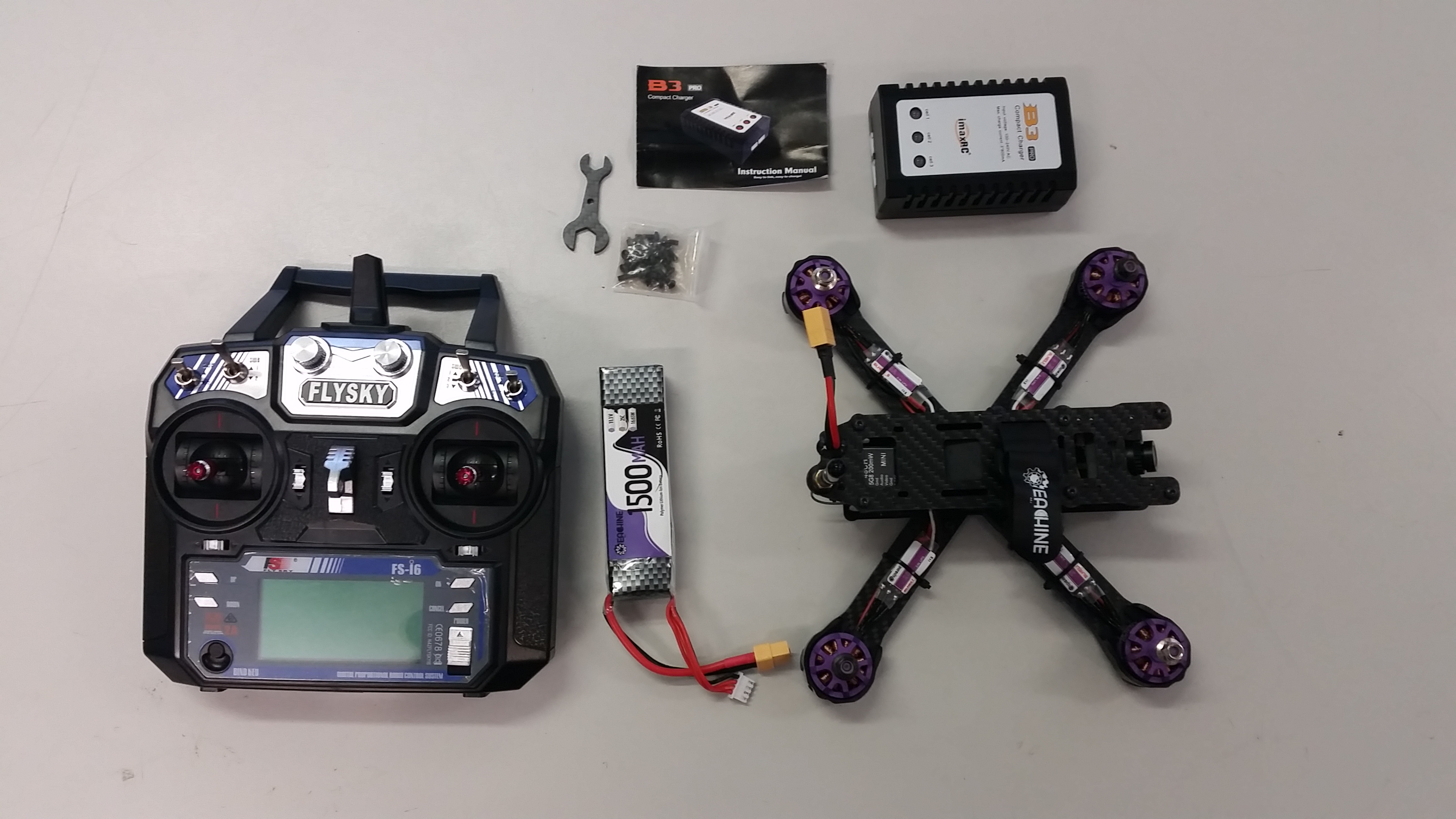
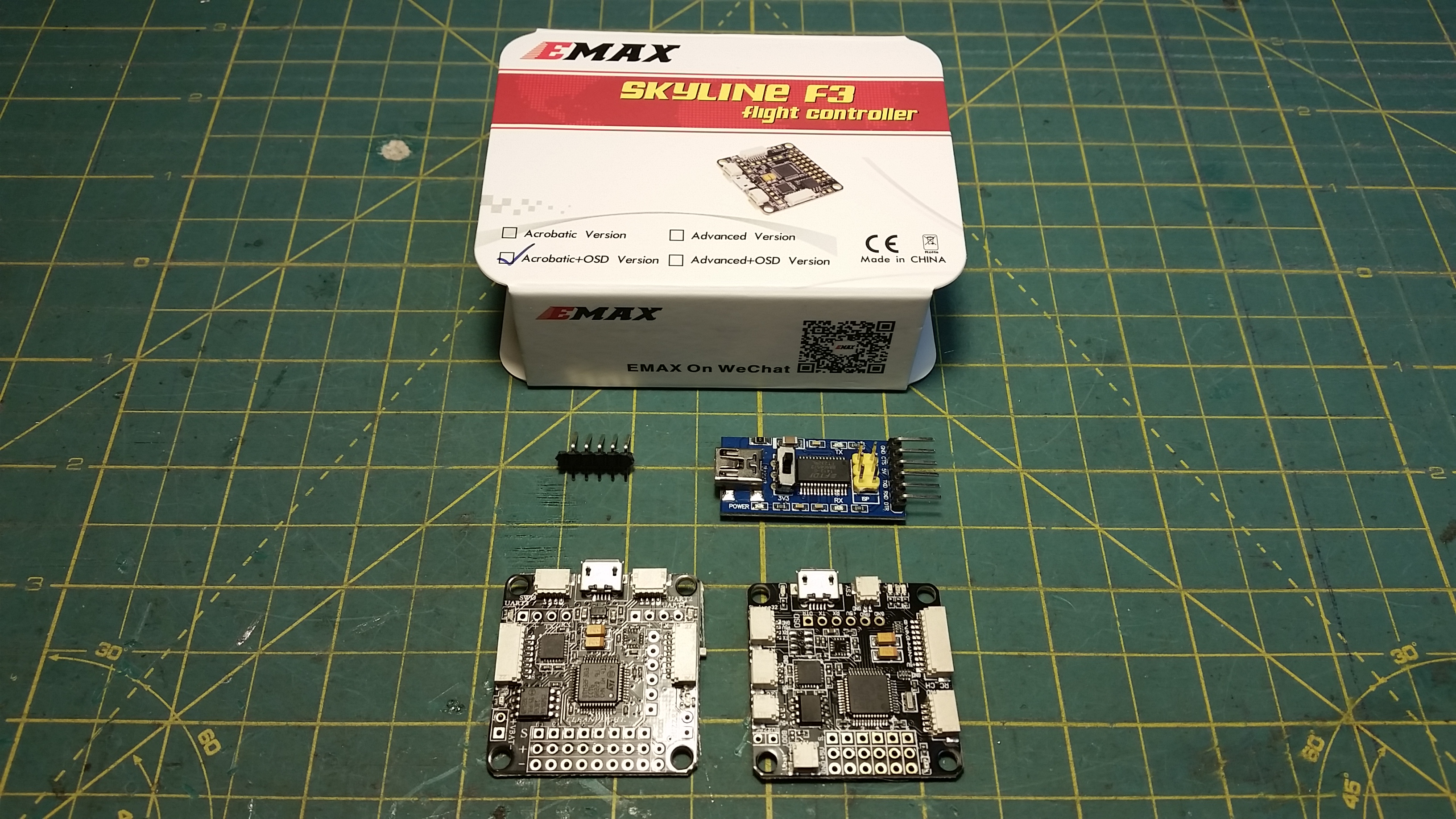
Components needed:
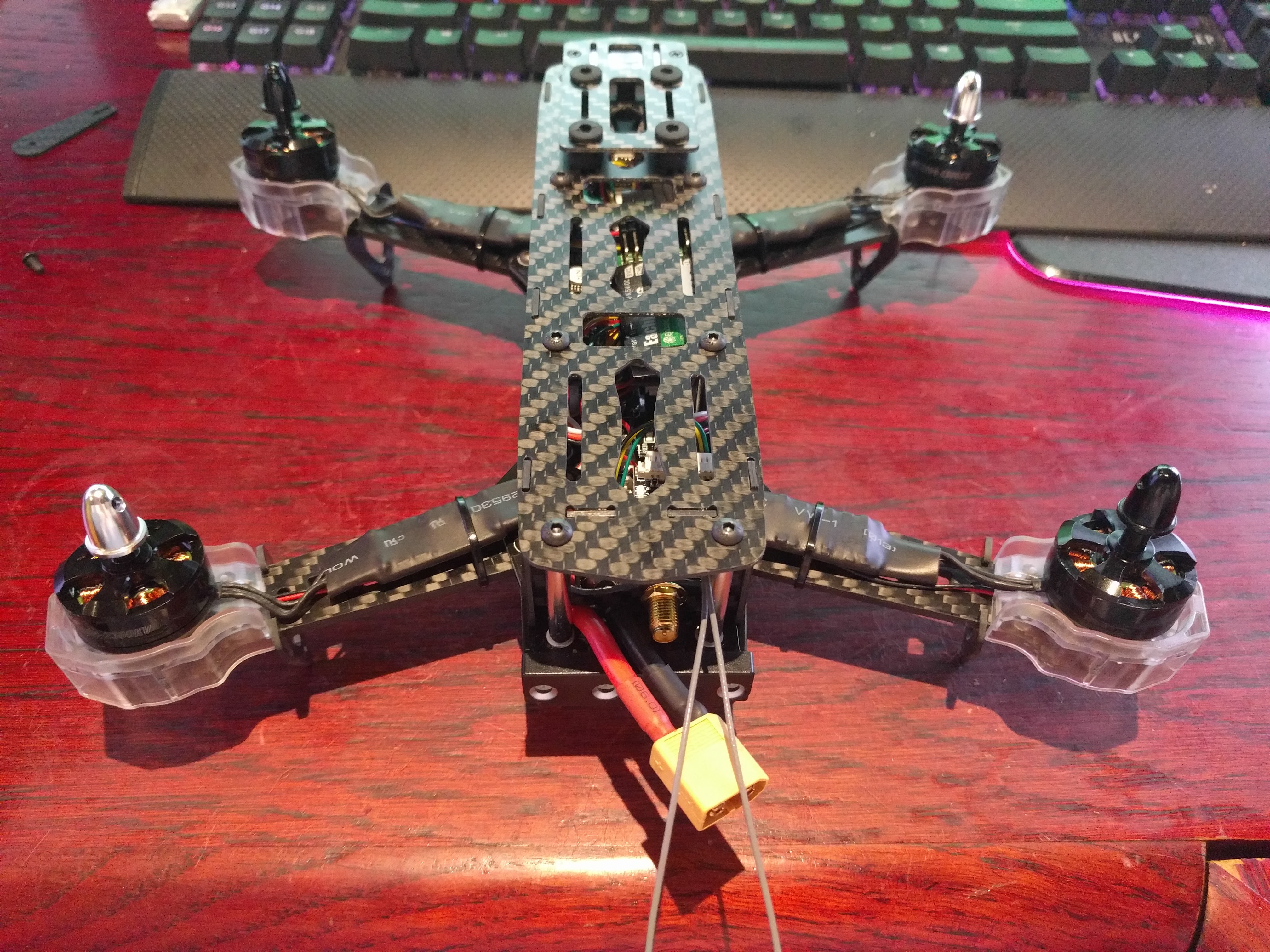
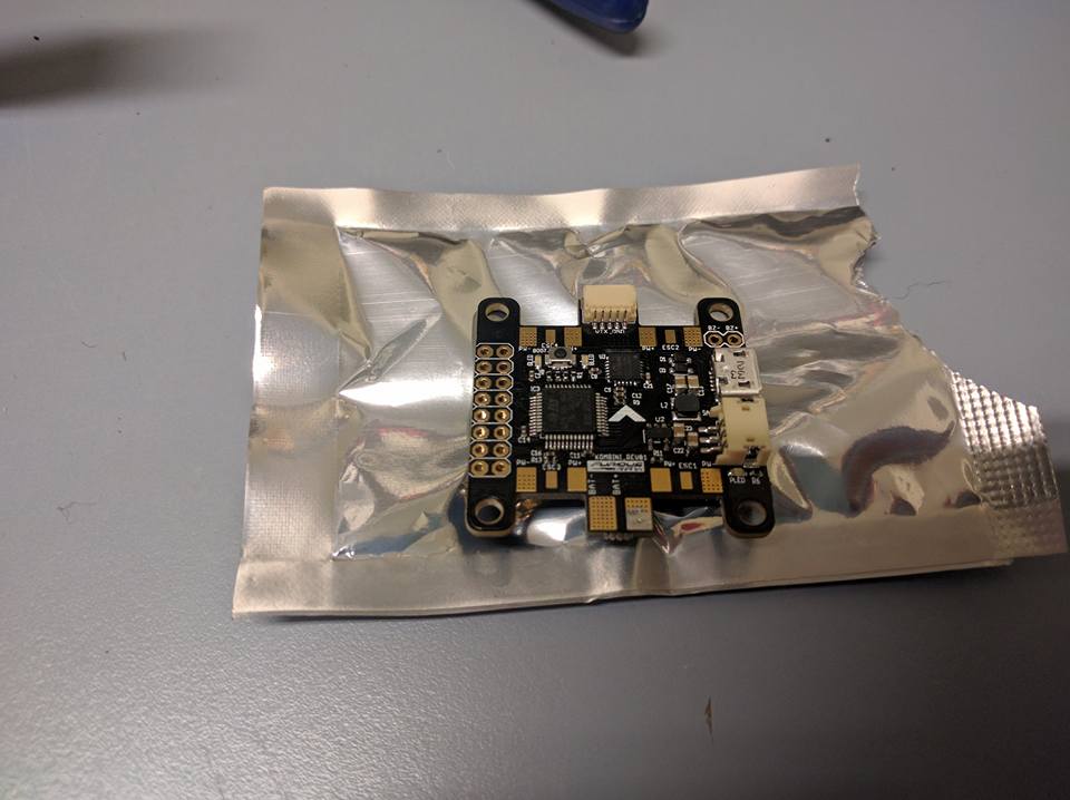
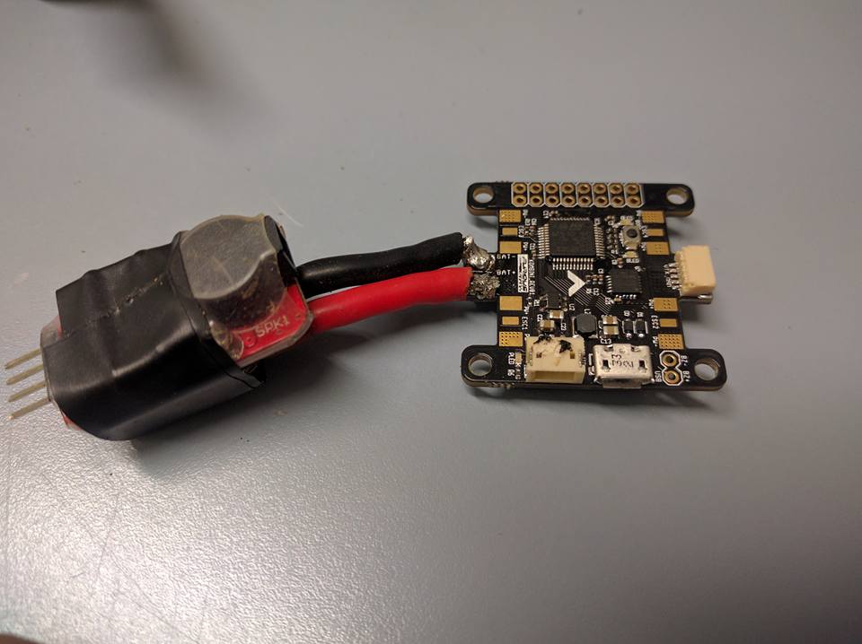
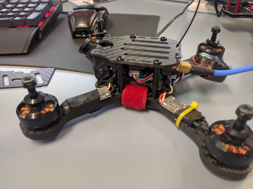
F1/F3 + OSD FC
FTDI adaptor and cable for connection to PC
Pin headers
Arduino and MWOSD software.
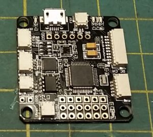
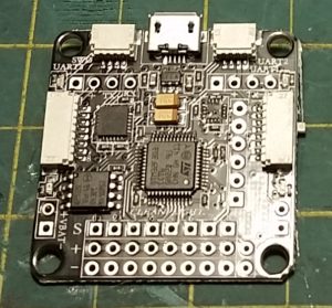
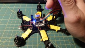
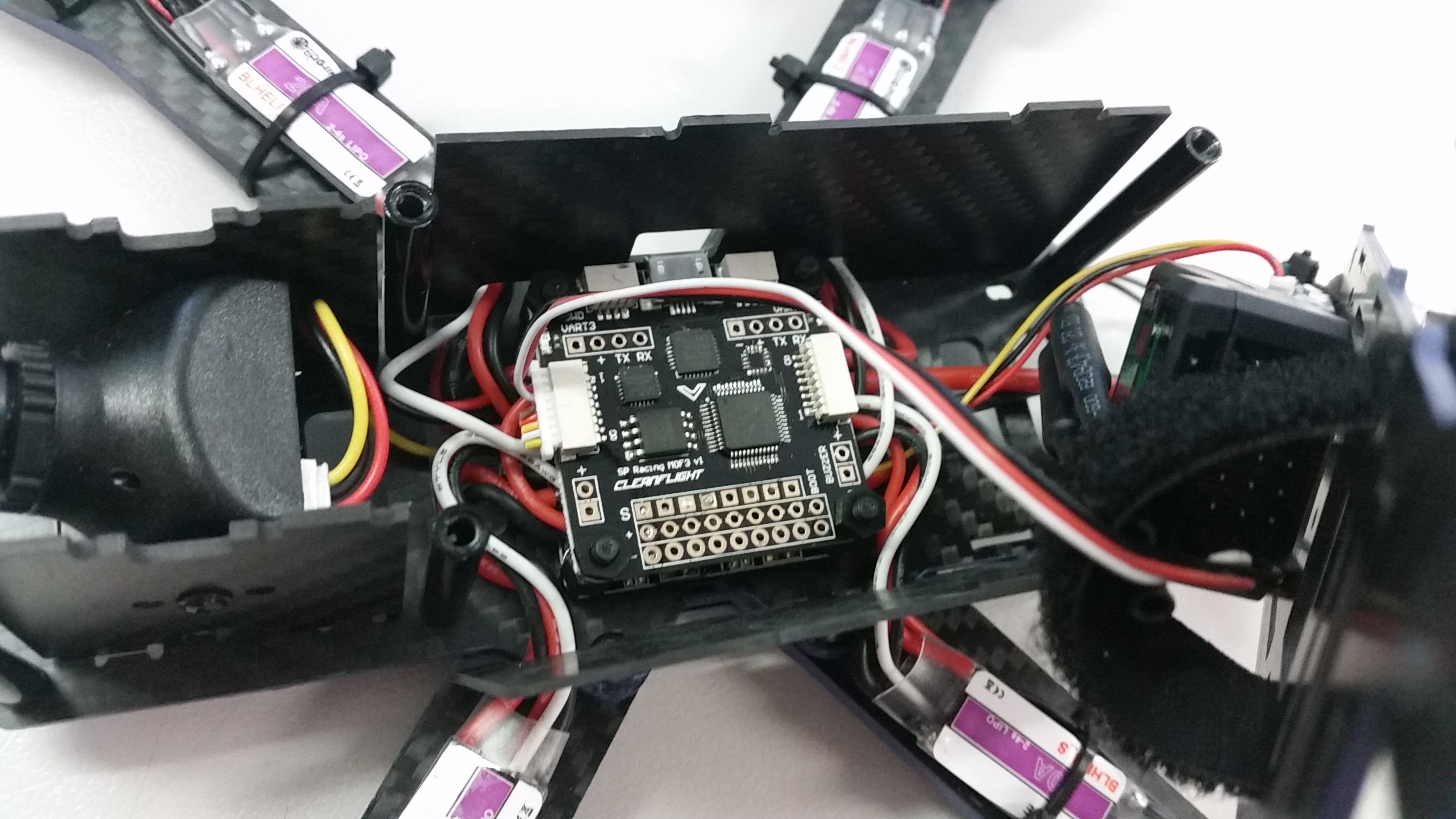
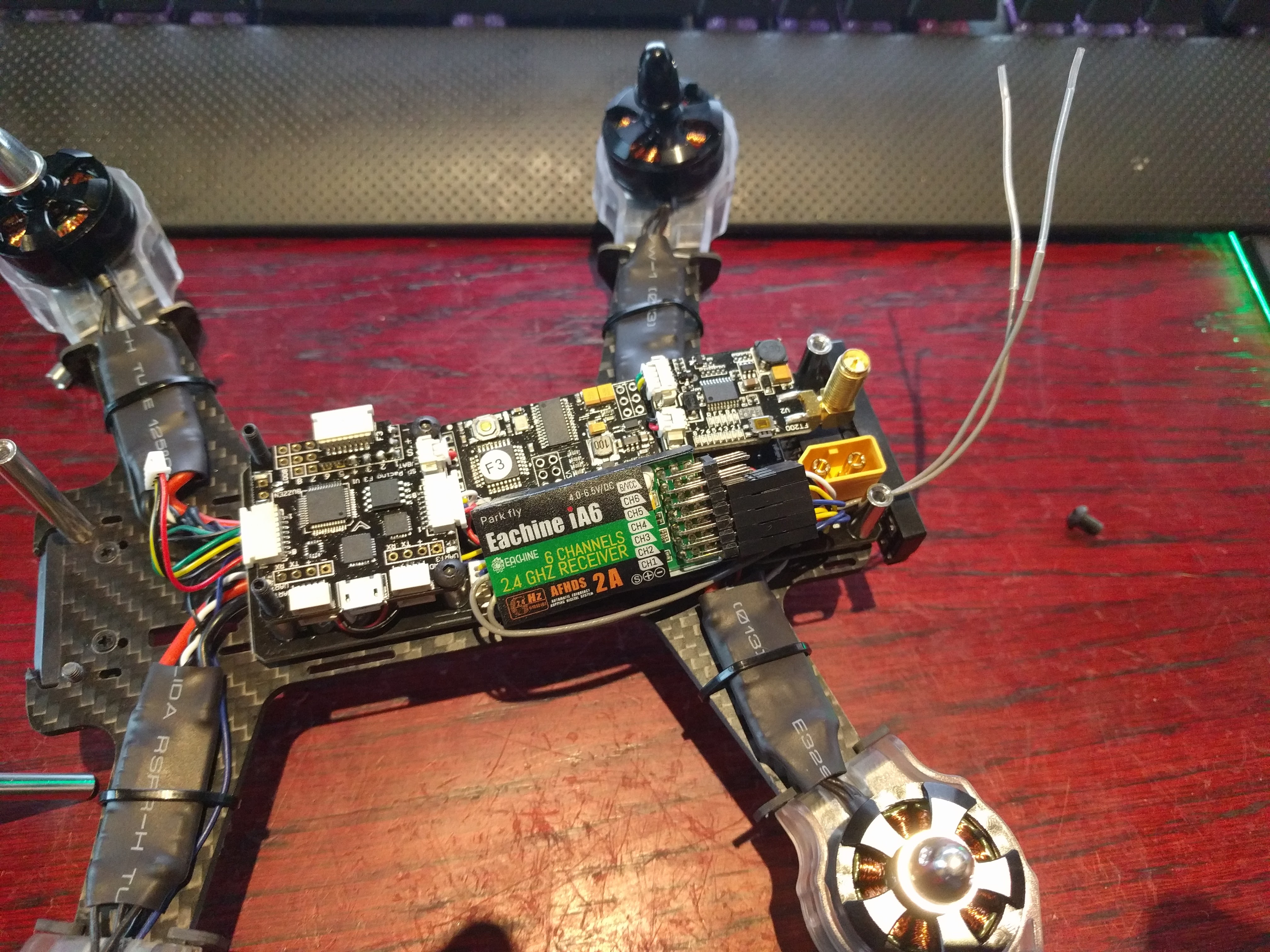
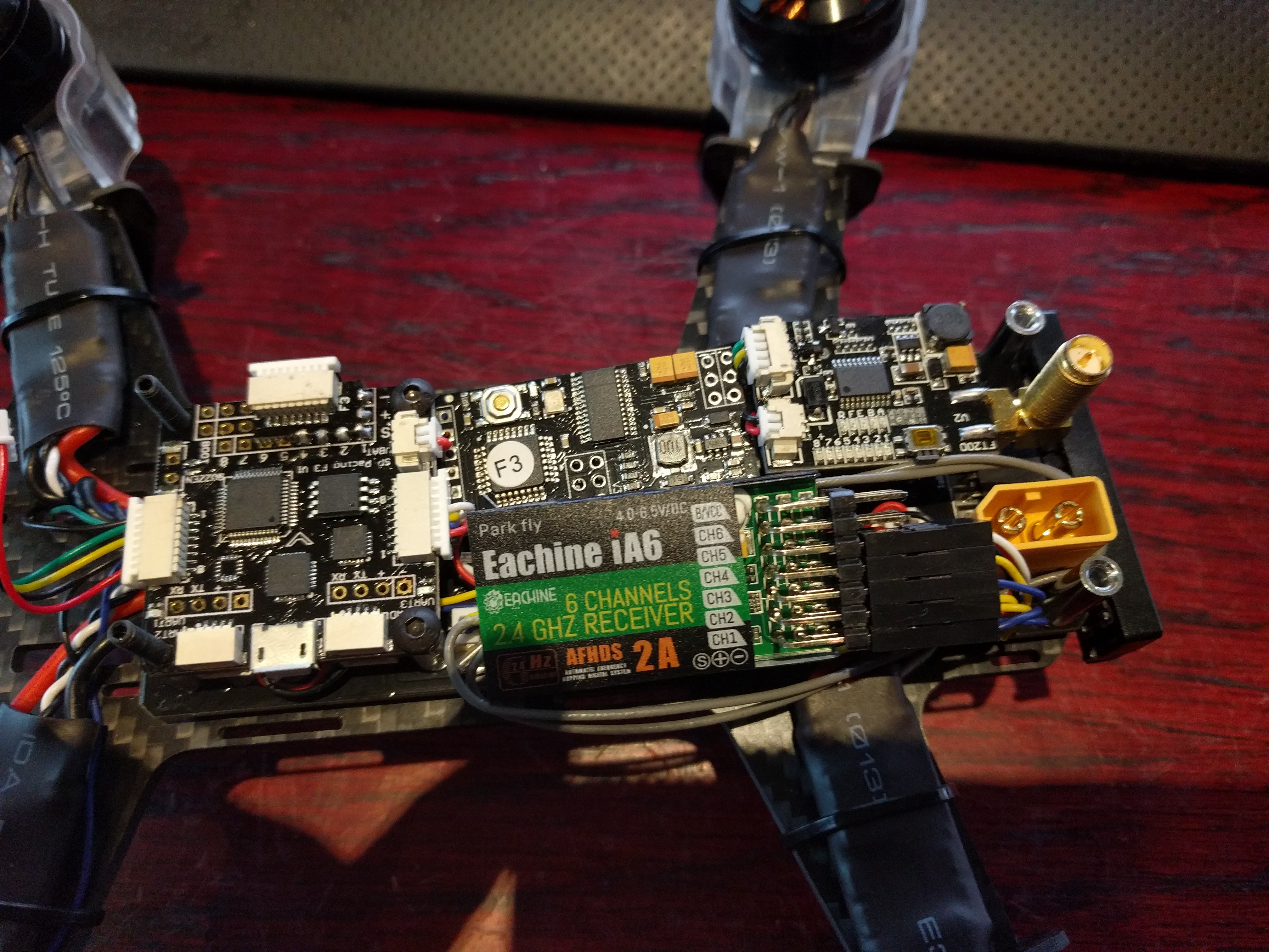
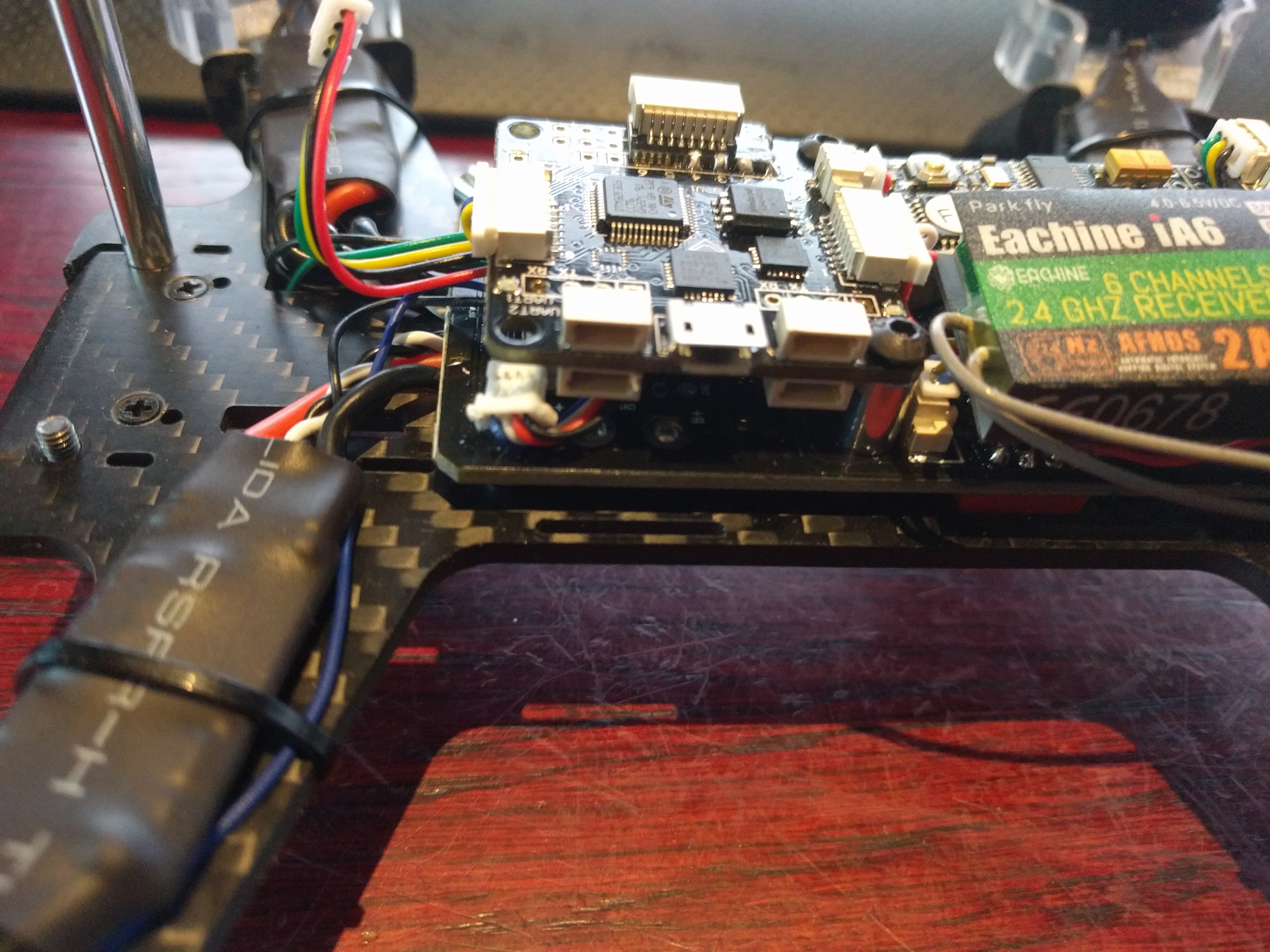
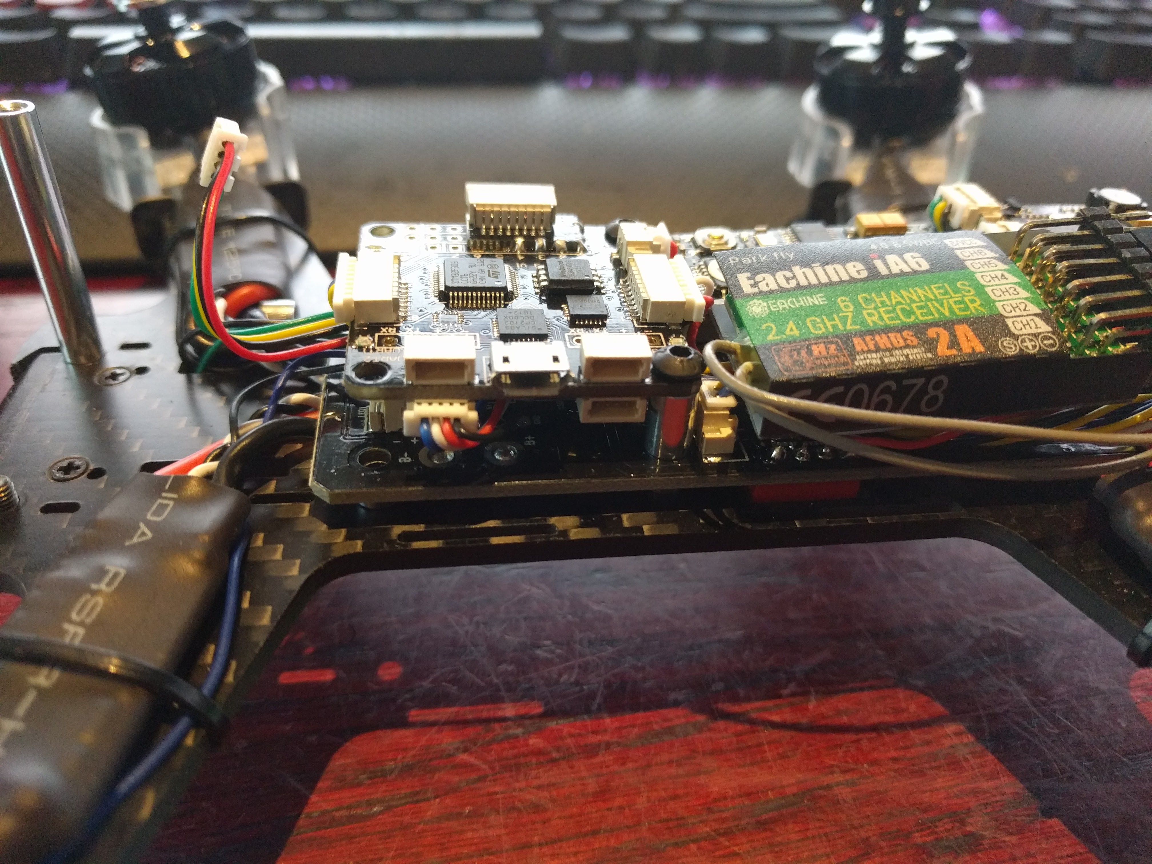
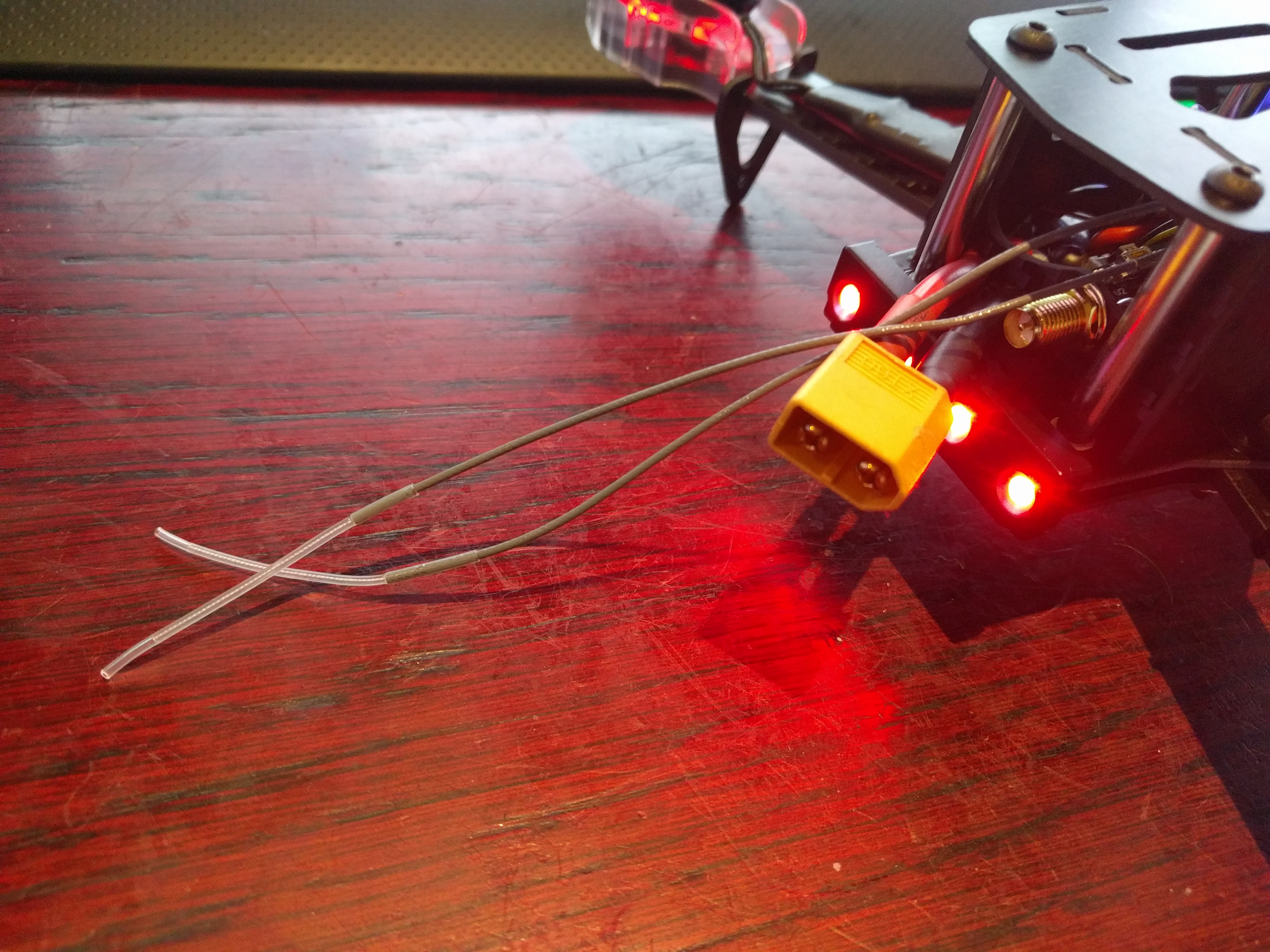
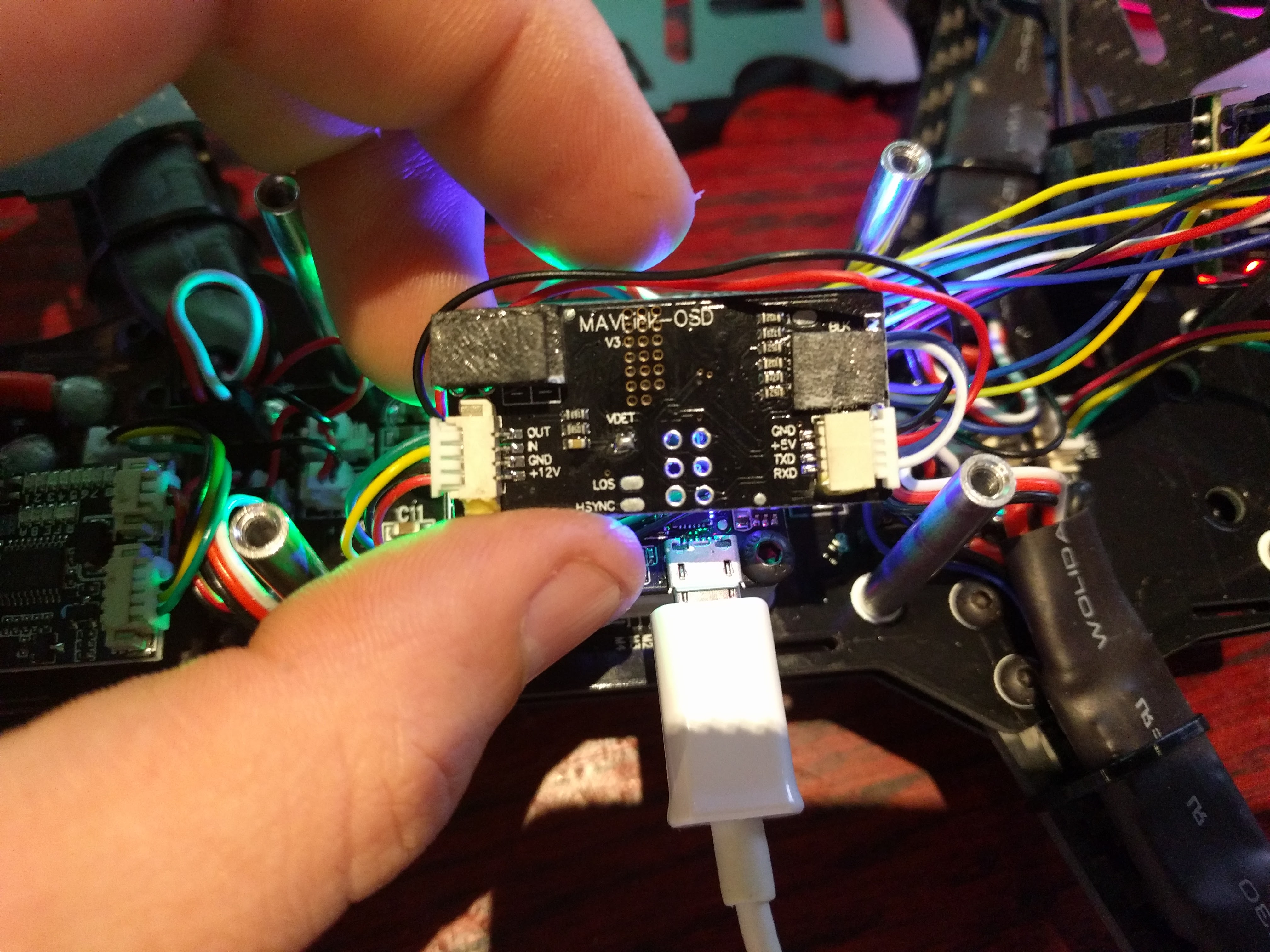
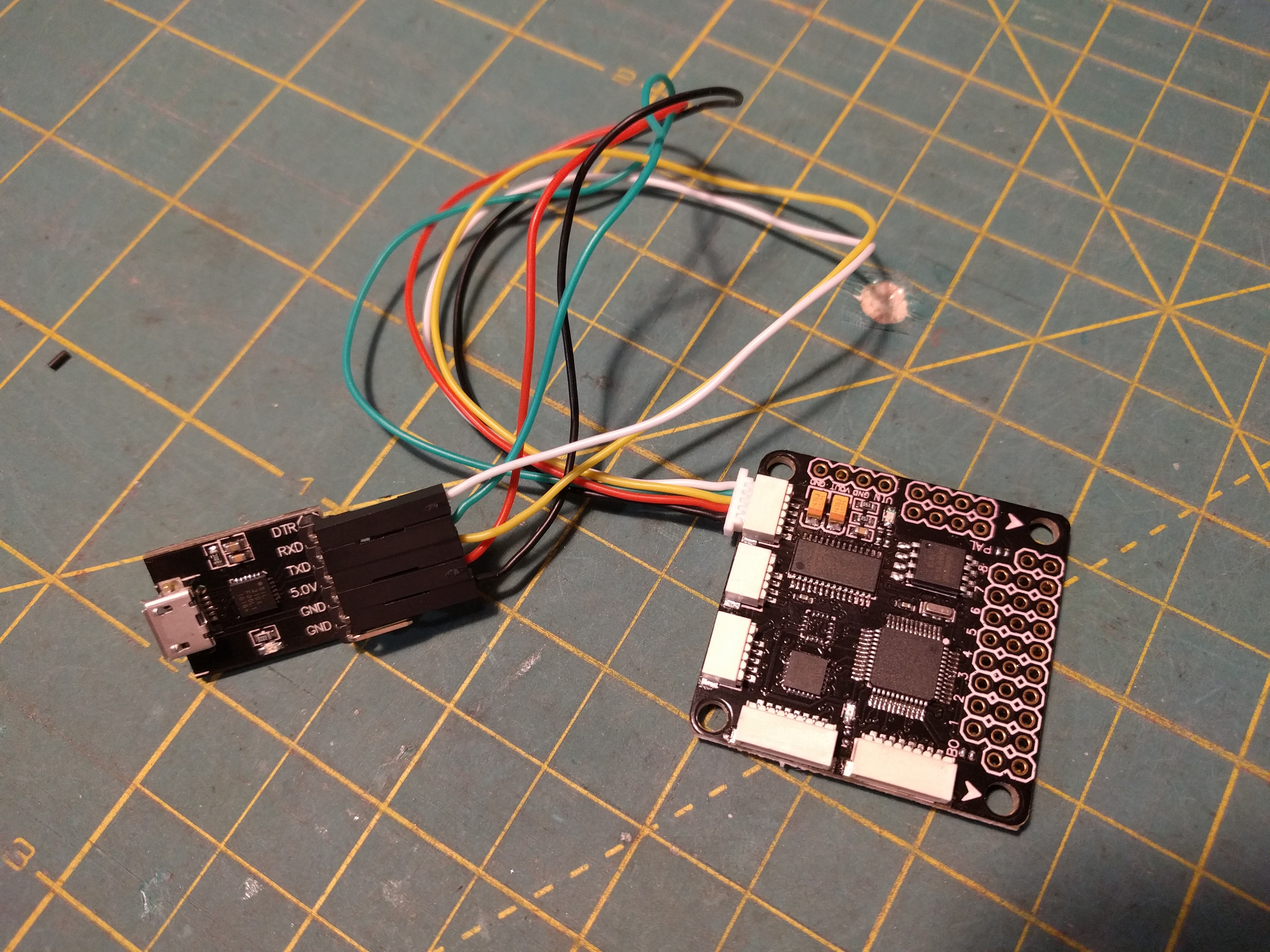
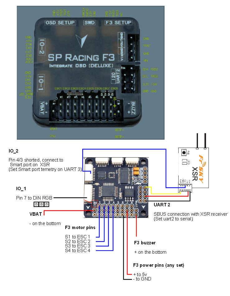
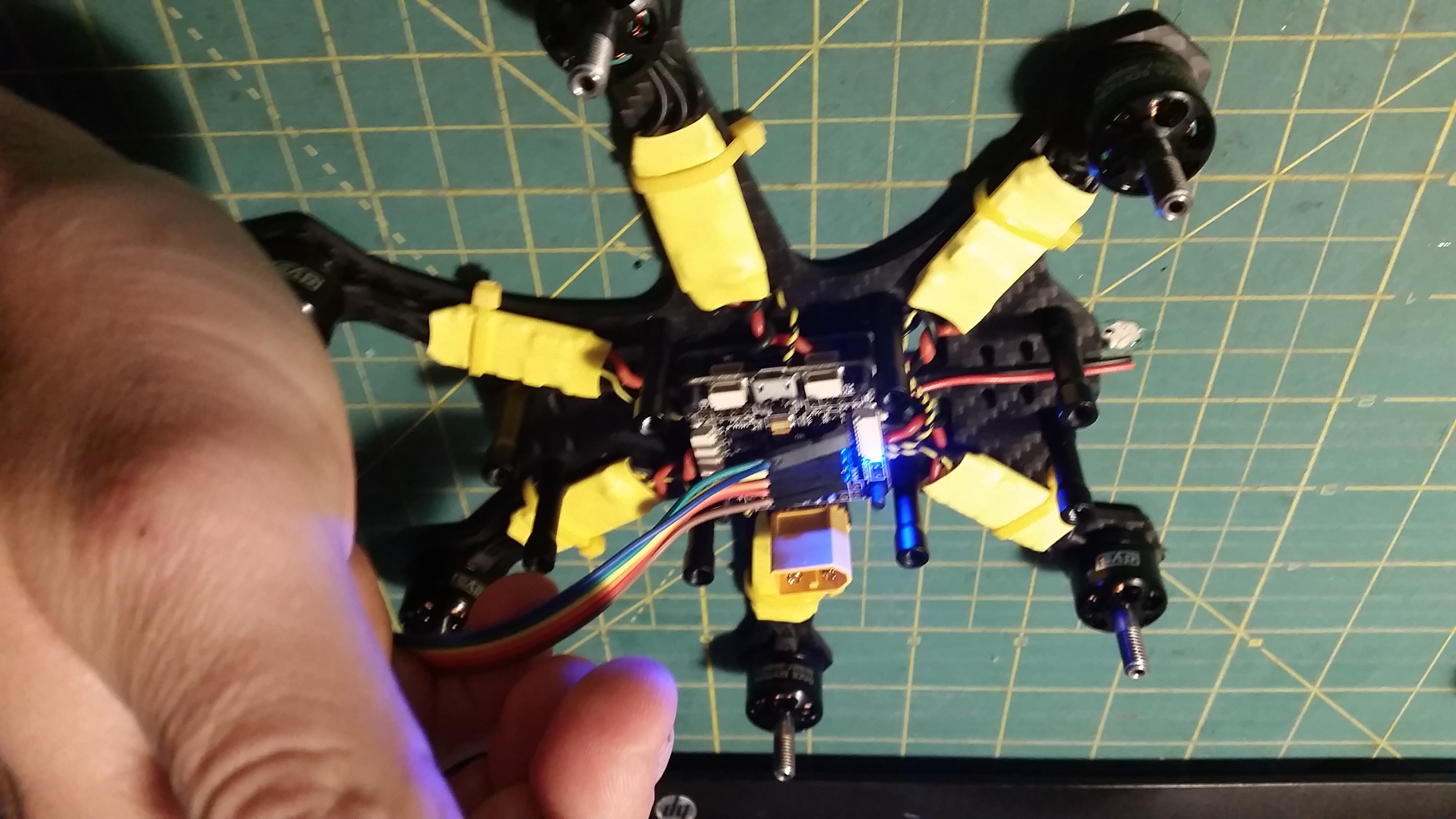
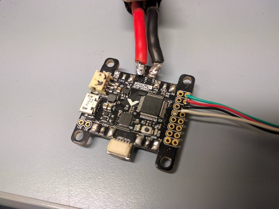
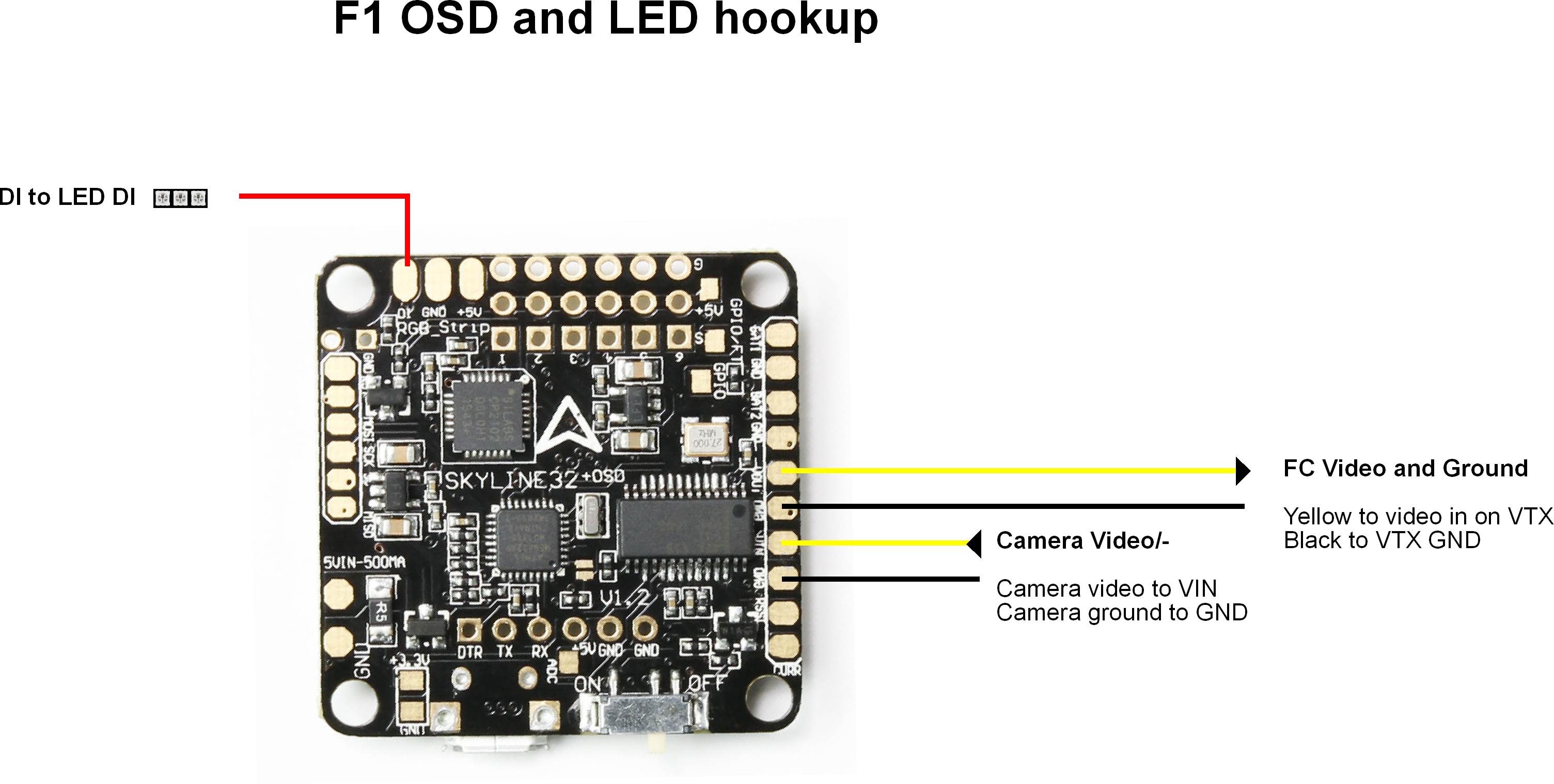
Your first step is to find the correct perforations on your flight controller that allow you to customise your OSD. They are marked:
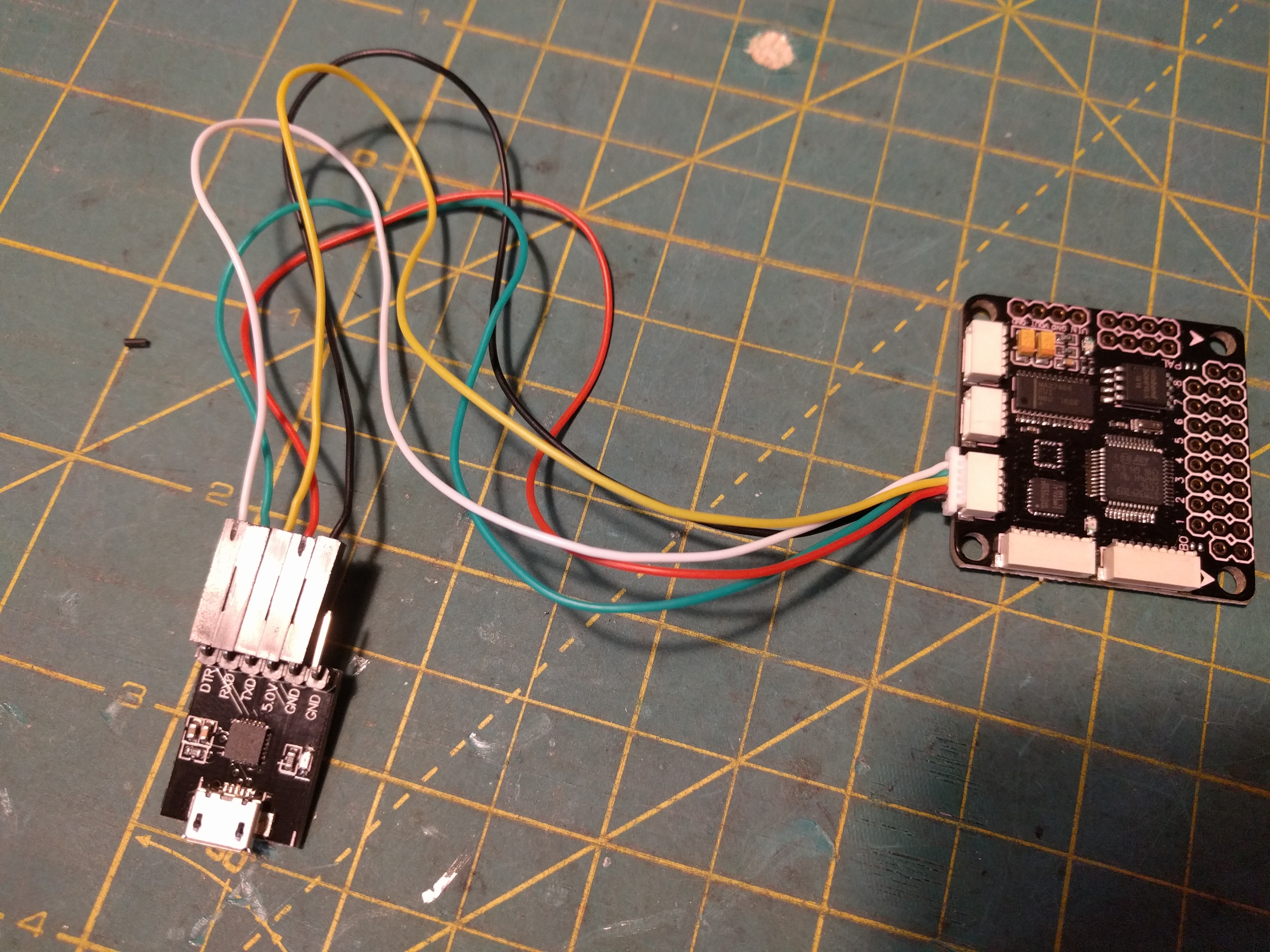
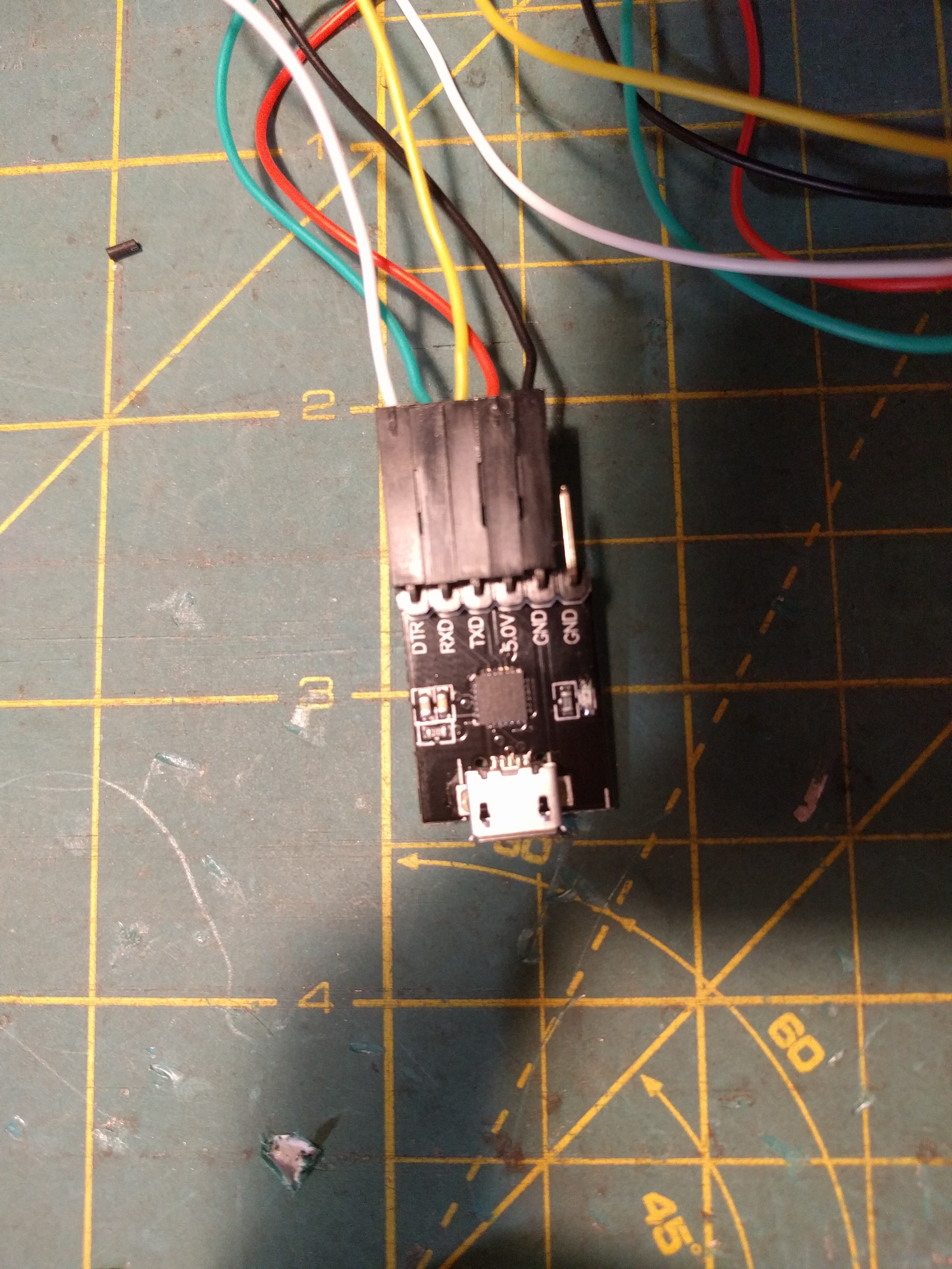
DTR/Tx/Rx/5V/GND/GND
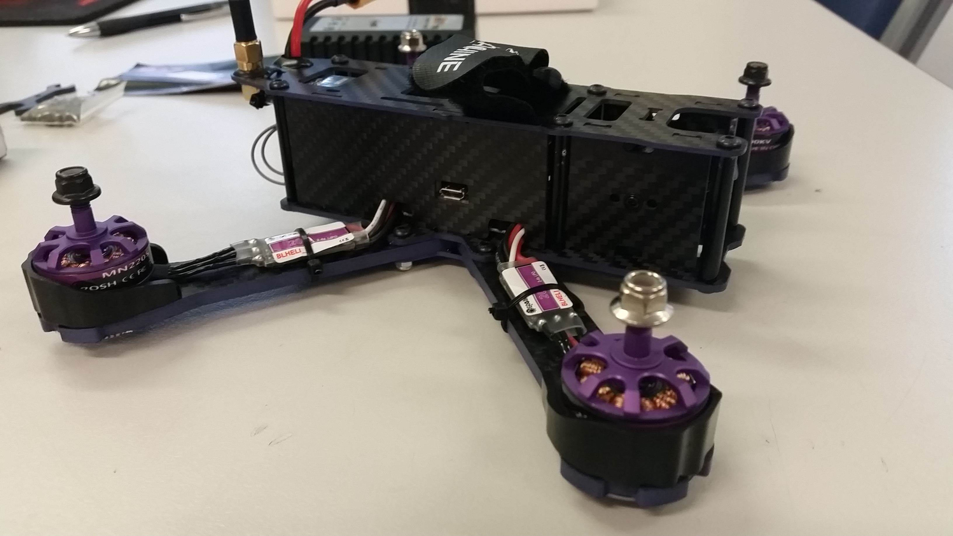
They can be seen on the F1 below the USB connector, and near the switch on the F3. The F3s ports are marked on the underside, and it would seem the Tx/Rx markings are reversed, depending on your perspective of things. Regardless, if you hook up Tx/Rx wrong you should get sync issues and not be able to flash it correctly, so if you are having issues look at this first.
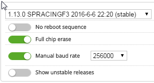
These pins are also mirrored on the FTDI adaptor, which can come in many different forms. Here is the one Ill be using. Its important to check that it is configured for 5v operation if you intend to power the OSD off the FTDI during the programming process. This one has a switch for 3.3v or 5v near the USB port.
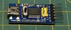
You will also see a pin labeled CTS, it is not needed in this instance. The pins should line up for direct connect, minus this CTS, so you can use single/double dupont connectors (servo) to match each pin to its counterpart on the FC. If you dont want to solder pins into the FC you can use a row of header pins and just hold them in place on the FC for the next few steps. If you ever need to reflash or reconfigure you will need them again, so keep a set aside for this purpose.
SOFTWARE:
Download and install Arduino and familiarise yourself with the basics.
Download Scarab OSD. Match the pins up via your temporary wiring harness.
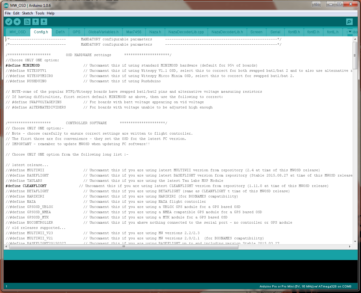
Once connected you need to open the Arduino file found inside the Scarab OSD folder called MW_OSD and check some of the settings on the Config.H tab.
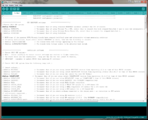
There is alot of parameters you can change here but everything should be set how we need it by default. Double check #define CLEANFLIGHT is chosen.
Under the Tools/Board menu in Arduino check that Arduin pro or Pro mini 5v/16 MHz ATmega328 is selected and that you are on the right port.
Now hit upload in the top left hand corner of arduino. It should start compiling and then upload. If you have any errors check that your ports are correct and that TX/RX is connected the right way.
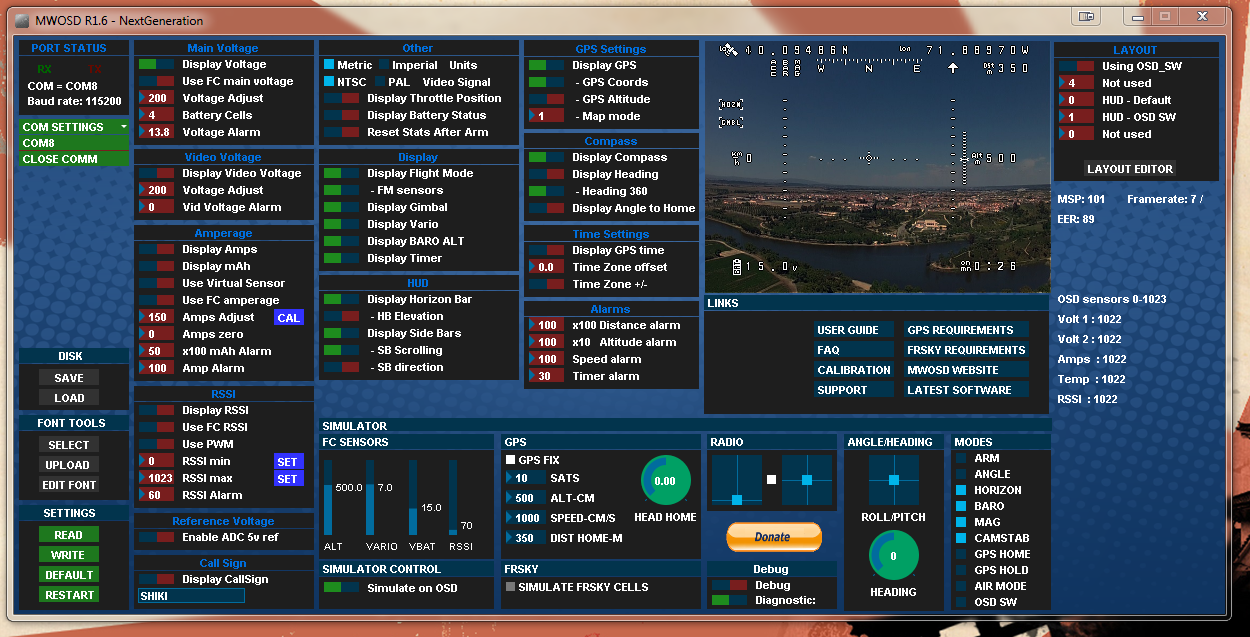
Once this is complete you can close down arduino and open up MW_OSD_GUI. You should see your available COM port, select it and hit READ.
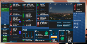
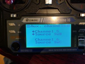
Select your FONT first and write it to the board. Once this is done you can pick and adjust all your display options. Make sure you select USE FC MAIN VOLTAGE for voltage display, this will use the voltage reading from Cleanflight, assuming you have connected Vbatt.
Make sure you have written any changes and thats it. Your OSD is now ready to use.


